
Quick Start Guide


6
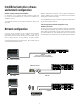
Input connections
Analog Inputs
Analog inputs are available on two standard XLR-F latching connectors.
The inputs are electronically balanced. The impedance is 20 kohms, and
the inputs can accept a maximum input level of +26 dBu.
Polarity is as follows:
Pin 1 = screen (shield), pin 2 = positive (+), pin 3 = negative (-).
Analog Links
Two latching XLR-M connectors are adjacent to the analog input
connectors and are paralleled to the input connectors to provide an
unprocessed analog loop-through to feed additional IPD Series units
or other equipment.
AES3 Inputs
A latching XLR-F connector accepts an AES3 digital audio signal. Input
impedance is 110 ohms. (Ensure that 110 ohm digital audio cables are
used; standard XLR microphone cables are rarely suitable for reliable
digital audio transmission.)
AES3 is a stereo digital format, and therefore both inputs are fed via a
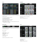
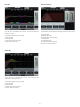
single connector. Selection of the analog or digital inputs is made via
the front panel display or IntelliDrive Controller software.
AES3 Link
A latching XLR-M connector is tted adjacent to the AES3 input
connector. This is an active link which sends an unprocessed
AES3 loop-thru to feed additional IPD units. The design requires no
termination load when the unit is the last connected.
Fig 1
Channel 1 sent
through to top box.
Channel 2
Channel 1 and 2
Channel 1
Output connections
Two types of power output connections are available on IPD
Series ampliers: Neutrik speakON and binding post. The
two types are connected in parallel. Loudspeakers may be
connected to both at the same time, but this is generally not
recommended as total impedance may be too low.
Binding Posts
Power outputs for loudspeaker connection are available on two fully
enclosed binding posts. Observe signal polarity as indicated.
speakON Connectors
Outputs for both channel 1 and channel 2 are available on a four-pole
speakON connector to the left. The two-pole speakON to the right
connect to output 2 only. See diagram for output connection and
polarity.
*see g 1
NOTE! When connecting wiring to Speaker Terminals, the installation
shall be made by an instructed person or ready-made leads or cords
shall be used
Bridge Mode
The IPD Series employs an inherently bridged Class D output topology;
Under no circumstances should the IPD Amplier be bridged, this may
cause undesired operating performance.