
Quick Start Guide


7
DSP configuration
Default conguration
IPD Series ampliers are shipped with default DSP settings that allow
immediate use in many common applications with no need for further
DSP conguration. The default mode is suited for use with the stereo
program into full range loudspeakers. The main signal routing and
parameter settings are as follows:
Input mixer:
Analog 1 and AES1 are routed to Ch. 1
Analog 2 and AES 2 are routed to Ch. 2
AES3 to analog failover is OFF Output Mute: Muted
Mode: Stereo Output EQ: Flat
Input levels: 0 dB Delay: Off
Input EQ: Flat Crossover: Off
Output levels: 0 dB
Fig 2
Analog 1
Analog 2
AES 1
AES 2
Input 1
Levels
Input 1
EQ
Input 1
delay
Output 1
Levels
Output 1
EQ
IDEEA
Amplifier
Output 1
Delay
Clip Limiter
Clip Limiter
Rail Sense Limiter
SCVPLX-Over
Input 2
Levels
Input 2
EQ
Input 2
delay
Output 2
Levels
Output 2
EQ
IDEEA
Amplifier
PSU
Output 2
Delay
SCVPLX-Over
Input
Mixer
Fig 3
Presets
Load
Store
Meters
Mixer
I/O Meters
Input 1 & 2
Gain
Delay
Link
Imput
Mixer
Device Config
Mode
Lock
LCD
Brightness
Device
Name
Device Info
Serial
Number
Temperature
Reading
Mac
Address
IP Address
H/W Version
Software
Version
Output 1 & 2
Gain Delay
Link
Limiter
Threshold
X-Over
LPF
HPF
Phase
Norm/
Invert
Enable
Type
Freq
Gain
Q / BW
PEQ 1-10
Enable
Type
Freq
Gain
Q / BW
PEQ 1-10
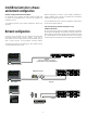
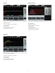
Signal ow block diagram
The block diagram below shows the signal ow from inputs to outputs.
*see g 2
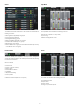
Front panel conguration
Input mixing and routing, as well as all DSP parameters, may be
congured using the Menu and Back buttons and the Adjust/Set rotary
encoder. The following menu tree is keyed to points in the signal ow
block in g 2.
*see g 3