USER MANUAL HEADLINES LAB 2002 USER MANUAL Unpacking 2 Warnings 2 User responsibility 2 1. 2. 3. Speaker damage Speaker output hazard. Radio interference. Introduction 1. 2. Installation 1. 2. 3. 4. 5. 6. 7. 8.
Unpacking User responsibility Carefully open the shipping carton and check for any noticeable damage. Every LAB.GRUPPEN amplifier is tested and inspected before leaving the factory and should arrive in perfect condition. If found to be damaged, notify the shipping company immediately. Only the consignee may institute a claim with the carrier, for damage incurred during shipping. Be sure to save the carton and packing materials for the carrier's inspection.
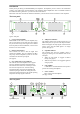
Introduction Thank you for purchasing a LAB.GRUPPEN power amplifier. The amplifier you have chosen is the culmination of many years of Research and Development. This amplifier makes amplification more controllable instead of the traditional "Boring black box" you have become accustomed to. Please take some time and read this manual to familiarize yourself with the advanced features of this amplifier. The front panel 6 3 4 5 6 VHF TEMP CLIP -5 -10 -15 CH. A CH.
Please refer to diagram on page 3 1. Speaker connector This type of speaker connector may be unfamiliar to some users. A full description is found in the operation section. (See page 6). 2. Minimum load selector (MLS™) switches These switches are used to select the minimum nominal speaker impedance the amplifier is going to drive. (See page 7). 3. Clip limiter switch. Turns the clip limiter on and off. (See page 9). 4. Input jack Alternative to using input XLR or for linking inputs with other amplifiers.
4. Grounding There is no ground lift switch or terminal on this amplifier. The signal ground is always floating via a resistor to chassis and the grounding system is automatic. If a potential above 0.6V presents itself between signal ground and chassis ground, a short circuit is introduced between the two, thereby enabling electrical protection. If a unit in the system is faulty, its mains fuse will blow, due to this automatic ground system.
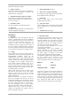
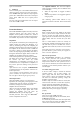
There are also TRS jacks for linking etc. They are wired as follows: balanced line. To minimize hum in the audio, use balanced inputs whenever possible. TIP HOT RING COLD SLEEVE SHIELD/GROUND Figure 8. Balanced line with unbalanced equipment Figure 4. TRS phone plug The input impedance is high enough (20 kohms balanced) to allow ”daisy-chaining”, or multiple parallel input connections. To daisy chain, use the TRS jacks provided on each channel.
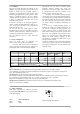
8. Impedance matching (MLS-switches) The MLS switches is located on the rear panel. The MLS ( Minimum load select ) switches offer a impedance matching, so you can drive the LAB 2002 in 2 ohms without increased heat losses. As stated earlier the LAB 2002 can produce at least 1100 watts into any impedance between 1.5 and 8 ohms. This is done with the aid of the MLSTM switches ( 2 ). The fixed positions shown in Table 2.
To obtain an output, connect the speaker leads to pin +1 on channel A Speakon to speaker positive terminal and pin +1 on channel B Speakon to speaker negative terminal . Do not connect either of the -1 (negative) pins of the Speakons. Do not connect speakers to channel A or B in the normal manner in bridge mode, as this can cause serious damage. The recommended minimum nominal impedance for bridged mono is 4 ohms (equivalent to driving both channels at 2 ohms).
Figure 13. Front indicators 5. Indicators The two bottom green ”ON” LEDs indicate that the output circuits are receiving the correct rail voltage. The ”-25 dB” LEDs glow when the output signal is greater than -25dB, 0dB is referenced to full output power. These LEDs also act as signal present indicators. The rest of the green LEDs forms a bar for output levels from -20dB to -5dB. Protection features Each LAB.
Design features Light weight The switch mode amplifiers has a very good power to weight ratio, (280w/Kg) making it one of the most powerful 2u amplifiers available.. The light weight is achieved not only by the PSU, but the IntercoolerTM and the 9 piece anodized alloy chassis contribute greatly, rear rack supports are unnecessary in most applications. Switch mode power supply (SMPS) Switch mode power supplies are the modern solution to the problems of size and weight.
Safety approvals LAB.GRUPPEN amplifiers are designed to meet the IEC65 (now called EN 60 065), a stringent electrical safety approval from the International Electrotechnical Commission. The IEC65 is recognized world-wide with most countries having an equivalent. EMC approvals EMC stands for Electro Magnetic Compatibility. This implies that the equipment should have low emission of radio frequencies, directly as electromagnetic fields in the air, and as conducted from the cables from and to the unit.
Appendix A Mains voltage selection LAB 2002 is normally shipped for 230 volt AC operation only. For export there is a 115/230 volt AC option available. To check if the amplifier is equipped with this option, please follow these steps: 1. Make sure that the LAB 2002 is unplugged from the mains voltage. 2. Remove the top and bottom cover. 3. If the four electrolytic capacitors close to the front are rated 385VDC, the amplifier is for 230 volt operation only 4.
Warranty and disclaimers • General This product is manufactured by LAB.GRUPPEN and is warranted to be free from defects in components and factory workmanship under normal use and service, for a period of one year from the date of original purchase. During the warranty period, LAB.