
Owner's manual


5
4. Grounding
There is no ground lift switch or terminal on this
amplifier. The signal ground is always floating via a
resistor to chassis and the grounding system is
automatic. If a potential above 0.6V presents itself
between signal ground and chassis ground, a short
circuit is introduced between the two, thereby
enabling electrical protection. If a unit in the system
is faulty, its mains fuse will blow, due to this
automatic ground system.
If however you wish to tie the signal ground to
chassis, connect the XLR-connector’s shell lug to
pin 1. In the interest of safety never disconnect the
earth pin on the AC cord.
For all units that are EMC approved (radio
interference), there is an AC mains filter. This filter
needs the chassis ground for reference, otherwise a
current loop is formed via the signal ground.
Use the balanced input to avoid hum and
interference.
5. Power consumption
There are three ways to determine the
power/current consumption of the amplifier:
First, the peak current draw at full output
power. Under this condition the power will trip the
wall breaker within 30 second and the amplifier
will operate for less than 2 minutes before
thermally limiting. During this time, the
temperature of the power supply will be stabilised
at a temperature that will have no effect on the
insulation rating of the AC line cord.
Secondly, the maximum expected average
current under worst case program material which is
1/3 of full power according to the FTC-standard. At
this level the music will be in the state of constant
clip and is therefore the highest power level one
can obtain without completely obliterating the
program.
At last, the "normal operating power", as
measured according to the safety standard IEC 65
and used by a majority of safety agencies. The
normal operating power is measured using pink
noise, with an average output power equal to 1/8 of
full power. The one eighth of the total power is as
loud as you can play music while making some
attempt to avoid obvious clipping. It also
corresponds to a headroom of 9dB, which is very
low for an audio program.
In 2 ohms operation, the protection of the amplifier
circuit will not permit long term current draw and
the component temperature rise will stabilises well
below the rating.
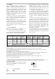
MAX OUTPUT POWER MAINS INPUT POWER
Power Full Power 1/3 Power 1/8 Power Idle
sine wave note 1 note 2
LAB 2002
8 ohms 2X 1100 3100 1300 700 130
4 ohms 2X 1400 4300 1700 900 130
2 ohms 2X 1400 4700 1700 900 130
note 1
Average power with music as program source Normal" music power with 9dB headroom,
The amplifier driven to clip level
note 2
IEC standard power rating.
Table 1.
The current draw can be calculated by dividing the mains input power by the mains voltage.
We recommend you to design the power distribution for at least the current at 1/8 power and 1/3 power for
heavy duty demands like discos etc.
The heat power can be calculated as the following example:
We consider a headroom of at least 9dB and a 4 ohms load on an amplifier producing 1400 watts per channel.
The 1/8 power per channel is then; 1400 / 8 = 175 watts, total output; 2 x 175 = 350 watts.
The power consumption according to the chart above is then 900 watts.
The heat power produced is the difference between the power consumption and output power;
900 - 350 = 550 watts per amplifier.
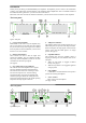
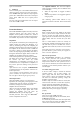
6. Input connections
XLR Input connectors are balanced and wired
according to the IEC 268, that is pin 2 hot, and wired
in the following way:
PIN 1 GROUND/SHIELD
PIN 2 HOT
PIN 3 COLD
Figure 3. XLR input connector pinout