
Owner's manual


8. Impedance matching (MLS-switches)
The MLS switches is located on the rear panel. The
MLS ( Minimum load select ) switches offer a
impedance matching, so you can drive the
LAB 2002 in 2 ohms without increased heat losses.
As stated earlier
the LAB 2002 can produce at least
1100 watts into any impedance between 1.5 and 8
ohms. This is done with the aid of the MLS
TM
switches ( 2 ).
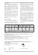
The fixed positions shown in Table 2. guarantee
1400 watts but higher powers can be achieved
Utilising higher MLS
TM
positions when connected to lower impedance's
see Table 2.
As you can see from Table 2 the LAB 2002 can produce in excess of
1400 watts.
Table 2.
OUTPUT CH.B
M
L
S
S
w
i
t
c
h
1+ CH.B+
1- CH.B-
0
-2
-4
-5
d
B
LAB 2002
LOAD CONFIGURATION -5 dB -4 dB -2 dB 0 dB
16 ohms Stereo (2 channel) 160 W 180 W 340 W 520 W
8 ohms Stereo (2 channel) 300 W 350 W 650 W 1100 W
4 ohms Stereo (2 channel) 570 W 680 W 1100 W 1400 W
1900 W [2]
2 ohms Stereo (2 channel) 1040 W 1200 W 1200 W 1400 W [1]
1400 W [2] 2900 W [2]
16 ohms Bridged mono 600 W 700 W 1300 W 2000 W
8 ohms Bridged mono 1200 W 1400 W 2200 W 2800 W
4 ohms Bridged mono 2100 W 2400 W 2400 W
2800 W
1
[1] Component tolerance dependent
[2] Continuous power, one channel driven or peak power both channels driven.
(Thermal protection may occur at high continuous power).
Power in watts (EIA 1 kHz, 1% THD)
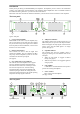
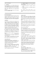
MLS SWITCH SETTING
Figure 10. MLS switches on rear panel
MLS
TM
positions can be different for each channel
and a variety of combinations can be achieved see
Table 3.
Channel Impedance MLS Power Comments
A 8 -2dB 650W Power
B 8 -2dB 650W reduction
A 4 0dB 1900W High peak
B 4 0dB 1900W power
A 8 0dB 1100W Power
B 2 -4dB 1200W matching
A 8 -2dB 650W Power
B 4 0dB 1900W sharing
Table 3.
The way to find the best MLS
TM
position for your
application is by experimentation, the amplifier is
very well protected (even down to 0.3 ohms), but
where speed is of essence stick to the fixed positions.
The thing to remember with the LAB 2002 that it is a
power converter and when you select MLS
TM
positions you are allocating a portion of power from
3000 watts.
Operation modes
1. Stereo operation
For stereo (dual channel ) operation, leave the Link
and Phase reverse switches in the undepressed
position. In this mode, both channels operate
independently of each other, with their level
attenuators controlling their respective levels.
Never connect either output terminal to ground
or in parallel. The recommended minimum
nominal impedance, for stereo or tandem operation,
is 2 ohms per channel.
2. Tandem mono
For tandem ( dual channel-single input) operation ,
depress the Link switch. Both channels can now be
driven by a signal, at either input connector. The
output connection is the same as in stereo mode.
You can use either TRS connectors for linking out
etc. Do not use the remaining XLR and TRS
connectors for mixing or other purposes. Both
level attenuators are active, allowing you to set
different levels for each channel.
Never connect either output terminal to ground
or in parallel.
3. Bridged mono
To bridge the amplifier, depress the Link switch (7)
and Phase reverse switch (6). Both channels are then
driven by a single signal at either input. You can
use any remaining input connectors for linking etc.
Do not use the remaining XLR and TRS as input
jacks simultaneously for mixing or other purposes.
7