USER MANUAL HEADLINES LAB 4000 USER MANUAL Rev. 3 Unpacking 2 Warnings 2 User responsibility 2 1. 2. 3. Speaker damage Speaker output hazard. Radio interference. Introduction 1. 2. Installation 1. 2. 3. 4. 5. 6. 7. 8. 9. 10. 8 Operation precautions Powering up -Soft start Input attenuators Gain switch Indicators Protections 1. 2. 3. 4. 5. 6. 7. 8 Stereo Tandem mono Bridged mono Stereo reverse Operation 1. 2. 3. 4. 5.
Unpacking User responsibility Carefully open the shipping carton and check for any noticeable damage. Every LAB.GRUPPEN amplifier is tested and inspected before leaving the factory and should arrive in perfect condition. If found to be damaged, notify the shipping company immediately. Only the consignee may institute a claim with the carrier, for damage incurred during shipping. Be sure to save the carton and packing materials for the carrier's inspection.
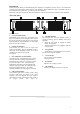
Introduction Thank you for purchasing a LAB.GRUPPEN power amplifier. The amplifier you have chosen is the culmination of many years of Research and Development. This amplifier makes amplification more controllable instead of the traditional "Boring black box" you have become accustomed to. Please take some time and read this manual to familiarize yourself with the advanced features of this amplifier. The front panel 6 3 4 5 6 8 9 VHF AFS TEMP AC CLIP -5 -10 -15 -20 CH. A CH.
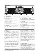
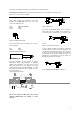
The rear panel INPUT 4 1 OUTPUT CH.A M LS S w i tc h Ga n i 2 9 dB Ga n i 4 1 dB CH. A Ln i k A+ B S w i tc h 5 dB d B M LS N o r m al P o .l B CH. B OUTPUT CH.B 7 8 6 S t e re o 4 5 R ev er se P o .l B 1 0 0 Mono Bridge -2 -2 1+ CH.B+ 1- CH.B- -4 -5 XLR Pin 1 On Off Clip Limiter Made in Sweden 2 Gnd 2 Pos 3 Neg Must be grounded 1/4“ Sleeve Tip Ring -4 On Off Clip Limiter 4000 230V AC 40-440Hz Power consumption: 2300 watts 3 9 Patent pend -5 Ser. N:o 1+ CH.
LAB.GRUPPEN switch mode amplifier use primary switching, i.e. the mains is rectified directly before the transformer, which means that the power supply is insensitive to the mains frequency and will operate from DC to 400 Hz. The amplifier is supplied with an approved European AC line connector.
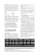
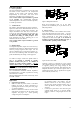
The power consumption according to the chart above is then 1300 watts. The heat power produced is the difference between the power consumption and output power; 1300 - 525 = 775 watts per amplifier. 8. Input connections XLR Input connectors are balanced and wired according to the IEC 268, that is pin 2 hot, and wired in the following way: PIN 1 PIN 2 PIN 3 GROUND/SHIELD HOT COLD Figure 6. Balanced line To connect an unbalanced source, tie pin 3 (ring on TRS jack) down to the shield of the connector.
9. Connecting speakers Speaker connections are made via the two Neutrik NL4FC Speakon connectors (1). They are the only connectors currently available to meet the EC safety requirements. They are wired in the following manner: Please note that this is the standard wiring convention for Speakon connectors adopted worldwide. Never connect either output terminal to ground or to some other output or input terminal (see warning on page 2).
Operation modes 1. Stereo operation For stereo (dual channel ) operation, leave the Link and Phase reverse switches in the undepressed position. In this mode, both channels operate independently of each other, with their level attenuators controlling their respective levels. Never connect either output terminal to ground or in parallel. The recommended minimum nominal impedance, for stereo or tandem operation, is 2 ohms per channel. 2.
VHF 2. Powering up -Soft start When you power up the amplifier it takes a couple of seconds to check its circuits (this is known as the "soft start" or "slow start" sequence), the fans then blow at high speed before going onto "idle" and the two bottom green LED’s come on to show the output circuits are receiving the correct rail voltage. TEMP CLIP -5 -10 -15 CH. A -25 -12 -10 4. Gain switch The gain switch located on rear panel is for changing the input sensitivity of the amplifier.
This is a useful feature as there are currently no commercially available compression drivers that can take 500 watts of power at 10 kHz!! this circuit is inaudible under normal use, however it can be turned off. If the VHF protection is required to be turned off i.e. for studio monitors, please consult your supplier, as this is a non-user adjustment. Short circuit protection All LAB.GRUPPEN amplifiers are completely short circuit protected.
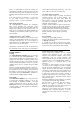
90 80 Voltage [V] 70 60 50 2 40 30 1 20 3 10 0 0 5 10 15 20 25 30 Current [A 35 40 45 50 Figure 14. Current-voltage characteristic of different power supply topologies. 1) Conventional power supply show voltage drop due to internal resistance 2) Regulated power supply used by LAB. 3) Unregulated switch mode power supply with current limiting.
LAB 4000 is normally shipped for 230 volt AC operation only. For export there is a 115/230 volt AC option available. To check if the amplifier is equipped with this option, please follow these steps: 1. Make sure that the LAB 4000C is unplugged from the mains voltage. 2. Remove the top and bottom cover. 3. If the four electrolytic capacitors close to the front are rated 1500uF 200VDC, the amplifier is for 230 volt operation only 4.
Warranty and disclaimers • General This product is manufactured by LAB.GRUPPEN and is warranted to be free from defects in components and factory workmanship under normal use and service, for a period of one year from the date of original purchase. During the warranty period, LAB.