
User guide


4
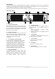
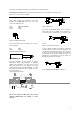
The rear panel
Figure 2. Rear panel
1. Speaker connector
This type of speaker connector may be unfamiliar to
some users. A full description is found in the
operation section. (See page 7).
2. MLS™ switches
These switches are used to select the maximum
output power . (See page 7).
3. Clip limiter switch.
Turns the clip limiter on and off. (See page 9).
4. Input jack
Altern a tive to using input XLR or for linking inputs
with other amplifiers. (See page 6).
5. Input signal XLR (See page 6).
6. Phase reverse switch for channel B
For reversing the input signal phase of channel B to
allow bridged operation. (See page 8).
7. Link switch
Allows a single input to drive both channels
simultaneously. (See page 8).
8. Gain select switch
Allows amplifier gain to be switched between 29dB
and its normal gain at 0.775mV input sensitivity.
(See page 9).
9. AC line cord (See page 5)
Installation
1. Mounting
The amplifier is two rack units high (2U) and will
mount in a standard EIA 19 inch rack. Amplifiers
may be stacked directly on top of each other. There
is no need for spacing between units. If it is the
intention to fill a rack with amplifiers, we
recommend racking is started from the bottom of
the rack. It is also recommended that rear supports
are used for amplifiers mounted in the middle of
the rack, especially if used as part of a portable
system.
2. Cooling
Your amplifier uses forced air cooling system to
maintain a low and even operating temperature. All
LAB.GRUPPEN amplifier, which are fan
ventilated, have front to rear cooling. There are
several reasons for this, one is that there's usually
cooler air outside the rack than inside and therefore
the amplifiers can run at higher continuos power
levels without thermal problems. Never try to
reverse the air flow, as the Intercooler® need a
pressure chamber between the fans and heat sink,
and this only works in one direction of the air flow
(see Design features on page 8).
Should a heat sink get too hot, its sensing circuit
will mute the hot channel. If the power supply
overheats, another sensing circuit will mute all
output channels, until it cools down to a safe
operating temperature.
Make sure that there is an adequate air supply in
front of the amplifier and that the rear of the
amplifier has sufficient space to allows the exhaust
to escape. If the amplifier is rack mounted, do not
use covers or doors on the front or rear of the rack.
For fixed installations with a central cooling
system, usually found in fixed installations with a
dedicated rack room, it may be necessary to
calculate the maximum heat emission. Refer to
Power consumption on page 5.
3. Operating voltage
A label just below the mains cable on the rear of
the amplifier indicates the AC mains voltage, for
which the amplifier is wired. Connect the power
cable only to the AC source referred to on the label.
The warranty will not cover damage caused by
connecting to the wrong type of AC mains.
For converting a 230 volt amplifier to 115 volt or
vice-versa, see Appendix A.
OUTPUT CH.B
MLS
Switch
0
-2
-4
-5
dB
Made in Sweden
230V AC 40-440Hz
CH. B
CH. A
INPUT
4000
XLR
Pin 1 Gnd Sleeve
2 Pos Tip
3 Neg Ring
1/4“
Ser. N:o Removed!
OUTPUT CH.A
MLS
Switch
0
-2
-4
-5
dB
Patent pend
Power consumption: 2300 wattsMust be grounded
Clip LimiterClip Limiter
On
Off
Mono Bridge
Rev er se Po l. B
Link A+B
Ga in 29 dB
Ga in 41 dB
Stereo
No rm al Po l. B
1+ CH.A+
1- CH.A-
1+ CH.B+
1- CH.B-
Clip Limiter
On Off
Clip Limiter
2
1
3 9 3 2
4 5 6 8 5
4 1
7