
User guide


6
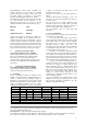
The power consumption according to the chart above is then 1300 watts.
The heat power produced is the difference between the power consumption and output power;
1300 - 525 = 775 watts per amplifier.
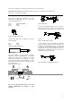
8. Input connections
XLR Input connectors are balanced and wired
according to the IEC 268, that is pin 2 hot, and
wired in the following way:
PIN 1 GROUND/SHIELD
PIN 2 HOT
PIN 3 COLD
Figure 3. XLR input connector pinout
There are also TRS jacks for linking etc. They are
wired as follows:
TIP HOT
RING COLD
SLEEVE SHIELD/GROUND
Figure 4. TRS phone plug
The input impedance is high enough (20 kohms
balanced) to allow ”daisy-chaining”, or multiple
parallel input connections. To daisy chain, use the
TRS jacks provided on each channel. The input
circuits also have a high enough headroom, to accept
the maximum output level from virtually any low
level signal source.
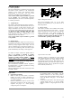
Figure 5. Rear panel connectors
Do not use XLR and TRS jacks on the same
channel simultaneously for mixing or other
purposes.
Figure 6. Balanced line
To connect an unbalanced source, tie pin 3 (ring on
TRS jack) down to the shield of the connector. If
you leave one pin disconnected, you will lose 6 dB
in gain.
Figure 7. Unbalanced line connection
A more optimal method for handling unbalanced
sources is shown in Figure 8.This is similar to the
connection for balanced lines, but pin 3 is tied down
to shield, at the source side instead. The hum and
noise rejection for the cable is equivalent to that for a
balanced line. To minimize hum in the audio, use
balanced inputs whenever possible.
Figure 8. Balanced line with unbalanced equipment
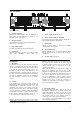
230V AC 40-440Hz
CH. B CH. A
INPUT
4000
XLR
Pin 1 Gnd Sleeve
2 Pos Tip
3 Neg Ring
1/4“
Power consumption: 2300 watts
Must be grounded
Mono Bridge
Rev er s e Pol. B
Lin k A + B
Ga in 29 dB
Ga in 41 dB
Ster eo
Normal Pol. B