
Operation Manual


3. Installation
8
PLM+ SERIES Operation Manual rev 3.0.4
2.3. Additional Documentation
This document, the PLM+ Operation Manual, serves as the primary reference source for detailed information
on the installation and operation of PLM+ Series Powered Loudspeaker Management systems. It also provides
For complete information on DSP configuration and operation using Lake Controller, please refer to the
Lake Controller Manual, available online at www.labgruppen.com/support.
For detailed information on configuration and operation of the power platform using CAFÉ, please refer to the guide
embedded in the software or to the CAFÉ Coach video series available on the Lab.gruppen
YouTube channel or via a link on www.labgruppen.com.
3. Installation
3.1. Unpacking
Carefully open the shipping carton and check for any damage to the device or the supplied accessories. Every
Lab.gruppen product is tested and inspected before leaving the factory and should arrive in perfect condition. If
any damage is discovered, please notify the shipping company immediately. Only the consignee may initiate a
claim with the carrier or their insurers for damage incurred during shipping. Save the carton and packing materials
for the carrier’s inspection.
In addition to the PLM+ Series device, the shipping carton includes the following items:
• PLM+ Series Quick Start & Field Reference Guide
• AC mains lead (power cable) with Neutrik® powerCON® connector
• Rear brackets for additional rack support (pair) along with associated mounting hardware
Please keep the original carton and associated packaging to facilitate shipping of the device should the need arise.
3.2. Mounting
top or bottom vents and therefore PLM+ units may be stacked directly on top of each other.
accommodate connectors and cables; allowance must be made for cable or loom bends within a rack.
3. Installation
PLM+ SERIES Operation Manual rev 3.0.4
9
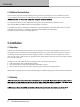
3.2.1. Rear Mounting
Two rear support brackets along with associated mounting hardware are included with the PLM+, as shown in
Figure 3.1; it is recommended that these are used wherever possible. Fit the brackets to the vertical rails at the rear
of the rack. Figure 3.2 and Figure 3.3 show the tting options for xed and removable installation.
The support brackets are reversible and may be tted to point either to the front or rear of the rack; the orientation
used depends on the rack depth and position of the rear rack rails.
Two mounting methods are possible; note that the method shown in Figure 3.2 additionally provides extra security
against unauthorized removal. For situations where rapid removal and replacement is required, the method shown
in Figure 3.3 should be used.
Fig 3.1: Rear support bracket with mounting hardware
Fig 3.2: Rear support bracket mounted for Fig 3.3: Rear support bracket mounted for
xed installation and bracket pointing forward removable installation and bracket pointing back
3. Installation
9
PLM+ SERIES Operation Manual rev 3.0.4