User’s Manual Labconco Coated Steel, Fiberglass and PVC Blowers Coated Steel Models 7068000, 7068100, 7068200, 7068300, 7068400, 7068500, 7068600, 7068700, 7068800, 7068900, 7069000, 7069100, 7069200, 7069300, 7069400, 7069500, 7069600, 7069700, 7071900 Fiberglass Models 7180000, 7180100, 7180200, 7180300, 7180400, 7180500, 7180600, 7180700, 7180800, 7180900, 7181000, 7181100, 7181200, 7181300, 7181400, 7181500, 7181600, 7181700, 7182000, 7182100, 7182200, 7182300 PVC Models 7183000, 7183100, 7183200 To
Copyright © 2002, 2007, 2010, 2014 Labconco Corporation. All rights reserved. The information contained in this manual and the accompanying products are copyrighted and all rights reserved by Labconco Corporation. Labconco Corporation reserves the right to make periodic design changes without obligation to notify any person or entity of such change. Warranty Labconco provides a warranty on all parts and factory workmanship.
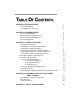
TABLE OF CONTENTS CHAPTER 1: INTRODUCTION About This Manual Typographical Conventions 1 2 3 CHAPTER 2: PREREQUISITES Location Requirements Mounting Support Requirements Electrical Power Requirements Space Requirements 5 5 6 6 6 CHAPTER 3: GETTING STARTED Unpacking Your Blower Install Blower on a Supporting Structure Adjust Blower Outlet Orientation Install Exhaust Run with Vibration Dampers Connect Blower Inlet for Coated Steel Blowers Connect Blower Inlet for Fiberglass Blowers Connect Blower Inlet for
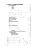
CHAPTER 6: MAINTAINING YOUR BLOWER Routine Maintenance Motor Bearings V-Belt Common Service Operations Pillow Block Bearing Replacement Motor Replacement CHAPTER 7: MODIFYING YOUR BLOWER, CALCULATING STATIC PRESSURE LOSS, AND BLOWER SIZING Two Main Blower Modifications Additional Modifications by Adding Ductwork Accessories Blower Sizing Example Sizes and Pressure Losses in Thermoplastic Duct Thermoplastic Duct Duct Couplings, Female Duct Couplings, Male Elbows Thermoplastic Duct Reducers Zero Pressure Weat
CHAPTER 1 INTRODUCTION Congratulations on your purchase of a Labconco Blower. Your Labconco Blower has been specifically engineered to meet the demanding requirements of most laboratory ventilation situations. The outside steel housing of the blower encloses the motor, shaft, and bearings. The contaminated air plenum of the Coated Steel Blower has a protective phenolic coating. The Fiberglass Blower features a fiberglass reinforced polyester housing and an injection molded polypropylene impeller.
Chapter 1: Introduction About This Manual This manual will help you learn how to install, use, and maintain your blower. Instructions for installing optional equipment on your blower are also included. Chapter 1: Introduction provides a brief overview of the blower, explains the organization of the manual, and defines the typographical conventions used in the manual. Chapter 2: Prerequisites explains what you need to do to prepare your site before you install your blower.
Chapter 1: Introduction Typographical Conventions Recognizing the following typographical conventions will help you understand and use this manual: Book, chapter, and section titles are shown in italic type (e.g., Chapter 3: Getting Started). Steps required to perform a task are presented in a numbered format. Comments located in the margins provide suggestions, reminders, and references.
Chapter 1: Introduction If you would like to review how blowers operate, or their differentiating features go to Chapter 4: Performance Data and Safety Precautions. For information on the operational characteristics of the blower, go to Chapter 5: Using your Blower. If your blower is installed and you need to perform routine maintenance on the blower, proceed to Chapter 6: Maintaining Your Blower.
CHAPTER 2 PREREQUISITES Before you install your blower, you need to prepare your site for installation. A dedicated source of electrical power must be located near the installation site. Carefully read this chapter to learn: The location requirements for your installation site. The mounting support requirements for your installation site. The electrical power requirements for your installation site. The space requirements for your installation site.
Chapter 2: Prerequisites Mounting Support Requirements You must provide vibration isolators, vibration mounting pads, and/or a roof curb support for proper mounting of the blower. Vibration isolators or vibration mounting pads are available from many sources such as a local industrial supply company. Labconco recommends supporting the blower with 5/16" diameter mounting hardware.
CHAPTER 3 GETTING STARTED Now you are ready to unpack, inspect, and install the blower. Read this chapter to learn how to: Unpack and move your blower. Install the blower on a supporting structure. Adjust the blower outlet orientation. Install the exhaust run with vibration dampers. Connect to the blower inlet. Connect to the blower outlet. Connect the electrical supply source. Adjust the fan speed and confirm blower performance. Connect the PVC Blower drain.
Chapter 3: Getting Started DO NOT RETURN GOODS WITHOUT THE PRIOR AUTHORIZATION OF LABCONCO. UNAUTHORIZED RETURNS WILL NOT BE ACCEPTED. IF YOUR BLOWER WAS DAMAGED IN TRANSIT, YOU MUST FILE A CLAIM DIRECTLY WITH THE FREIGHT CARRIER. LABCONCO CORPORATION AND ITS DEALERS ARE NOT RESPONSIBLE FOR SHIPPING DAMAGE. Do not discard the packing material for your blower until you have installed and tested the blower.
Chapter 3: Getting Started Removing these fasteners allows you to rotate the housing to one of the other desired outlet positions. Then insert the 8 fasteners and secure the blower housing in that specific position. 3. Reinstall the upper weathercover panel and you are ready for operation. ! CAUTION: Blower 7071900 must be installed with outlet positioned for upward discharge. This will ensure that the integral back draft damper assembly will work properly.
Chapter 3: Getting Started Connect to the Blower Inlet for Fiberglass Blowers FRP Fiberglass Blowers, model numbers 7180000 through 7180700, feature a 10-3/8" OD inlet ring. This inlet ring is suitable for use with 10-inch diameter PVC ductwork. The PVC ductwork will fit outside the inlet ring and should be fastened by sheet metal screws through the fiberglass inlet ring. A silicone sealant is to be used to seal between the ductwork and the blower inlet ring to prevent air or moisture leakage.
Chapter 3: Getting Started Connect the PVC Blower Drain The PVC Blower has a 1/2" NPT drain connection in the bottom of the housing. When this connection is used, it should be directed into a proper drain or into the exhaust duct for proper disposal. ! PVC CAUTION: Draining the blower housing directly onto the roof may cause damage to your roof due to the corrosive chemicals exhausted.
Chapter 3: Getting Started For Fiberglass Blowers FRP Fiberglass Blowers model numbers 7180000 through 7180700, feature a 10-3/4" ID outlet connection. Ten-inch diameter ductwork will slip into this connection and should be held by sheet metal screws through the housing. Silicone sealant should be used to seal any air leaks between the duct and blower outlet connection. Fiberglass Blowers model numbers 7180800 through 7181700, feature a 12-3/4" ID outlet connection.
Chapter 3: Getting Started wire directly to the exposed terminals inside the motor. A knockout has also been provided on the side of the motor for this purpose. Access the motor by removing the top weathercover of the blower base. This weathercover is held in position by machine screws, and once they have been removed, you will have access to both the motor and V-belt area of your blower.
Chapter 3: Getting Started 14 NOTE: WHEN THE WIRING FOR YOUR BLOWER HAS BEEN COMPLETED, CHECK FOR PROPER MOTOR ROTATION. THE MOTOR SHOULD OPERATE IN A CLOCKWISE ROTATION AS VIEWED FROM THE SHAFT SIDE TO OBTAIN PROPER ROTATION OF THE IMPELLER WHEEL. WHEN IN OPERATION, THE IMPELLER SHOULD ROTATE COUNTERCLOCKWISE WHEN VIEWED FROM THE BLOWER INLET.
Chapter 3: Getting Started ! CAUTION: This blower contains an electrical motor, which requires proper electrical connection per the National Electrical Code (NEC) Section 430 to prevent hazards. This NEC code and local codes may require that a circuit disconnect, overload protection, and short circuit protection be included in the installation. Please consult the code or have the unit connected by a licensed electrician.
Chapter 3: Getting Started 6. Once the sheave is adjusted to the correct spacing, secure the set screw on the front half of the sheave. 7. Raise the motor up on the gravity belt tightener, and reinstall the belt on both sheaves. 8. Turn the blower back on at the roof disconnect. 9. Check the motor current with an ammeter to ensure it is in its proper operating range. Consult Chapter 4 for amperage specifications for your particular model. 10. Verify the hood face velocity is in its proper range.
CHAPTER 4 PERFORMANCE DATA AND SAFETY PRECAUTIONS Specifications and Performance Data The specifications and performance data for your particular model are listed and sub-grouped by Coated Steel, Fiberglass, and PVC Blowers. Blower curves are printed and listed on Labconco’s website at www.labconco.com.
Chapter 4: Performance Data and Safety Precautions 18 Product Service 1-800-522-7658, International 816-333-8811
Chapter 4: Performance Data and Safety Precautions Product Service 1-800-522-7658, International 816-333-8811 19
Chapter 4: Performance Data and Safety Precautions 20 Product Service 1-800-522-7658, International 816-333-8811
Chapter 4: Performance Data and Safety Precautions Product Service 1-800-522-7658, International 816-333-8811 21
Chapter 4: Performance Data and Safety Precautions 22 Product Service 1-800-522-7658, International 816-333-8811
Chapter 4: Performance Data and Safety Precautions Product Service 1-800-522-7658, International 816-333-8811 23
Chapter 4: Performance Data and Safety Precautions 24 Product Service 1-800-522-7658, International 816-333-8811
Chapter 4: Performance Data and Safety Precautions Product Service 1-800-522-7658, International 816-333-8811 25
Chapter 4: Performance Data and Safety Precautions 26 Product Service 1-800-522-7658, International 816-333-8811
Product Service 1-800-522-7658, International 816-333-8811 400 3.00 3.25 3.50 3.75 4.00 4.25 4.50 4.75 5.00 5.25 500 600 700 800 900 1100 1200 Flow Rate (CFM) 1000 2100 RPM 1300 2010 RPM 1400 Blower Performance Curve P/N 7071900 1500 1920 RPM 1600 1845 RPM 1700 1800 1745 RPM Chapter 4: Performance Data and Safety Precautions 27 Static Pressure (in. w.g.
Chapter 4: Performance Data and Safety Precautions NOTE: FOR A COMPLETE PERSPECTIVE AND EXPLODED VIEWS OF YOUR PARTICULAR BLOWER, REFER TO APPENDIX A REPLACEMENT PARTS. Safety Precautions ! 28 Before attempting any service and/or maintenance on your blower, always disconnect the blower motor from its power source to prevent possible injury. Upon initial start-up, always wear protective eyewear. A qualified technician should certify the blower/hood system before it is initially used.
CHAPTER 5 USING YOUR BLOWER Normal Operation Once your blower has been fully ducted and electrically wired, it is ready for operation. The blower is normally activated from a switch on or near the fume hood. Laboratory work can resume when the blower is operational, so that any prevailing fumes and/or odors can be exhausted from the room. Work must cease prior to turning the blower off.
Chapter 5: Using Your Blower 30 Product Service 1-800-522-7658, International 816-333-8811
CHAPTER 6 MAINTAINING YOUR BLOWER Now we will review the suggested maintenance schedule and the common service operations necessary to maintain your blower for peak performance. ! Only trained and experienced certification technicians should perform some of the service operations after the blower has been properly decontaminated. The wrench icon precedes the service operations that require qualified technicians.
Chapter 6: Maintaining Your Blower Motor Under normal usage, the drip proof style motor will require that you add 3-4 drops of SAE 10 motor oil to each oil port on the motor after 25,000 hours of operation. Should your blower motor experience constant use, maintenance should be on an annual basis, to extend the life of the blower motor. Bearings The pillow block bearings on your blower are factory sealed and lubricated. Under normal operation, no further lubrication is required.
Chapter 6: Maintaining Your Blower Motor Replacement With the power disconnected, remove the upper weathercover, the V-belt, the mounting hardware that supports the NEMA 56 motor frame and remove the motor. Remove the wire leads to the motor plate. Re-install the new motor in reverse order.
Chapter 6: Maintaining Your Blower 34 Product Service 1-800-522-7658, International 816-333-8811
CHAPTER 7 MODIFYING YOUR BLOWER, CALCULATING STATIC PRESSURE LOSS, AND BLOWER SIZING Two Main Blower Modifications There are two main ways to modify the performance of your blower as listed in Chapter 3: Getting Started. One way is the adjustment of the blower outlet orientation. The other way is the adjustment of the fan speed to fine-tune the performance of your blower/hood system. Refer to Chapter 3 for these instructions.
Chapter 7: Modifying Your Blower ductwork length for your entire hood/blower system. Then the blower can be sized properly from the total equivalent resistance for your exhaust system. Blower Sizing Example: You have selected a Labconco Protector Premier 48 Laboratory Hood at 100 fpm and 730 CFM. The static pressure of the Protector Premier 48 at 100 fpm is 0.17". The exhaust collar of this hood is sized to receive 12" diameter PVC duct directly.
Chapter 7: Modifying Your Blower Nominal Diameter/Inches Actual OD/inches Actual ID/inches Catalog Number Shipping Wt./lbs. 6 6.625 6.25 47086 20 Airflow/CFM 250 500 750 1000 1250 1500 1750 2000 2500 3000 4000 5000 .039 .147 .321 .557 .855 -------- 8 10 12 8.625 10.750 12.750 8.250 10.375 12.375 47189 70272 56020 35 50 65 Static Pressure Loss/Inches H20 For Each 10 ft. of Duct Length .011 .003 .001 .037 .013 .005 .079 .026 .011 .140 .043 .018 .210 .066 .027 .300 .095 .039 .380 .130 .053 .485 .155 .
Chapter 7: Modifying Your Blower Duct Couplings, Male PVC duct in 6" length facilitates connections between Coated Steel Blowers and elbows, thermoplastic duct reducers and weather caps. Nominal Diameter/Inches Catalog Number Actual OD/Inches Actual ID/Inches Shipping Wt./lbs. 6 21447 6.625 6.250 3 8 47199 8.625 8.250 4 10 70278 10.750 10.375 5 12 70673 12.750 12.375 6 Elbows 45° Elbow 90° Elbow PVC elbows both 45° and 90°, are compatible with thermoplastic duct.
Chapter 7: Modifying Your Blower Zero Pressure Weathercaps The zero pressure weathercap is made of strong, corrosionresistant PVC. The cap adds little static pressure to the exhaust system and allows for vertical discharge of the effluent air for dispersion away from the building. Nominal Diameter/Inches Catalog Number Height/Inches Shipping Wt./lbs.
Chapter 7: Modifying Your Blower Blower Transition Adaptors This epoxy-coated steel transition adaptor fits all Labconco Coated Steel Blowers. This adaptor allows you to connect round thermoplastic duct to the exhaust side of the blower to create an exhaust stack. Nominal size PVC duct fits inside the adaptor opening. Nominal Diameter/Inches Catalog Number 8 10 12 47224 4722401 70034 Shipping Wt./lbs.
Chapter 7: Modifying Your Blower Accessory for Basic 47 Hoods Exhaust Transition Adaptor The exhaust transition adapts to 7" and 10" rectangular outlet on Basic 47 Hoods, model series 22473 and 22475, to receive 10" diameter PVC duct. Nominal Diameter/Inches 10 Catalog Number 22648 Shipping Wt./lbs. 5 Accessory for Perchloric Acid Applications Wash Rings Wash rings are suited for use in Perchloric acid duct systems.
Chapter 7: Modifying Your Blower Backdraft Dampers Designed for use in buildings under negative pressure to keep outside air from entering the laboratory through the hood ventilation system. Damper is weighted to stay in down/resting position when the hood is not in use, and rises from the airflow exhausting when the blower is on. It mounts vertically on blower outlet. The damper is made of PVC Type 1, unplasticized, schedule 40 duct. Nominal Diameter/Inches Catalog Number Shipping Wt./lbs.
CHAPTER 8 TROUBLESHOOTING Refer to the following table if your blower fails to operate properly. If the suggested corrective actions do not solve your problem, contact Labconco for additional assistance. PROBLEM Remote blower won’t operate. CAUSE Wires not connected at junction boxes or switches. Circuit breakers tripped in building electrical supply. Blower wiring is disconnected. Belt broken. Blower motor is defective. Contamination outside of fume hood.
Chapter 8: Troubleshooting PROBLEM (Cont’d.) Remote blower has excessive vibration. Fume hood has improper face velocity. CAUSE Inspect wheel for damage. CORRECTIVE ACTION Replace damaged wheel. Check for objects in blower wheel. Improper inlet connection. Remove objects in blower wheel. Blower not sized properly. Blower requires RPM adjustment. 44 Review Chapter 3: Getting Started. The blower inlet should be installed with a vibration damper or flexible duct connection.
APPENDIX A BLOWER REPLACEMENT PARTS The following illustrations and replacement parts are organized into four sub-groups of blowers, which are low pressure coated steel, low pressure fiberglass, high pressure fiberglass, and low pressure PVC. See the correct sub-group.
Appendix A: Blower Replacement Parts Coated Steel Models 7068000 through 7069700, 7071900 46 Product Service 1-800-522-7658, International 816-333-8811
Appendix A: Blower Replacement Parts Coated Steel Models 7068000 through 7069700, 7071900 Product Service 1-800-522-7658, International 816-333-8811 47
Appendix A: Blower Replacement Parts Coated Steel Models 7068000 through 7069700, 7071900 48 Product Service 1-800-522-7658, International 816-333-8811
Appendix A: Blower Replacement Parts Low Pressure Fiberglass Models 7180000 through 7181700 Product Service 1-800-522-7658, International 816-333-8811 49
Appendix A: Blower Replacement Parts Low Pressure Fiberglass Models 7180000 through 7181700 50 Product Service 1-800-522-7658, International 816-333-8811
Appendix A: Blower Replacement Parts Low Pressure Fiberglass Models 7180000 through 7181700 Product Service 1-800-522-7658, International 816-333-8811 51
Appendix A: Blower Replacement Parts Fiberglass Blower Models 7182000 through 7182300 52 Product Service 1-800-522-7658, International 816-333-8811
Appendix A: Blower Replacement Parts Fiberglass Blower Models 7182000 through 7182300 Product Service 1-800-522-7658, International 816-333-8811 53
Appendix A: Blower Replacement Parts PVC Blower Low Pressure Models 7183000 through 7183200 54 Product Service 1-800-522-7658, International 816-333-8811
Appendix A: Blower Replacement Parts PVC Blower Low Pressure Models 7183000 through 7183200 Product Service 1-800-522-7658, International 816-333-8811 55
Appendix A: Blower Replacement Parts 56 Product Service 1-800-522-7658, International 816-333-8811
APPENDIX B BLOWER DIMENSIONS Product Service 1-800-522-7658, International 816-333-8811 57
Appendix B: Blower Dimensions 58 Product Service 1-800-522-7658, International 816-333-8811
Appendix B: Blower Dimensions Product Service 1-800-522-7658, International 816-333-8811 59
Appendix B: Blower Dimensions 60 Product Service 1-800-522-7658, International 816-333-8811
APPENDIX C BLOWER ENVIRONMENTAL CONDITIONS Environmental Conditions Maximum altitude: 9843 feet (3000 meters). Ambient temperature range: -30° to 130°F (-34° to 54°C). Main supply voltage fluctuations not to exceed ±10% of the nominal voltage. Transient over-voltages according to Installation Categories II (Over-voltage Categories per IEC 1010). Temporary voltage spikes on the AC input line that may be as high as 1500V for 115V models and 2500V for 230V models are allowed.