
Manual

Labconco Instruction Sheet 3909400, Rev. F, ECO F288 1 of 7
LABCONCO CORPORATION 8811 Prospect Ave, Kansas City, MO 64132
(816) 333-8811, Fax (816) 363-0130, (800) 821-5525
Guardian™ Digital Kit No 3908800, 02 or 3908801, 03
Guardian Digital 1000 Operation
The Guardian Digital Airflow Monitor consists of the airflow sensor, the Alarm Unit and the 15
VDC power supply. For 115V operation the alarm unit is powered by plugging the power
supply into the factory-prepared digital airflow monitor socket. For 230V operation, the Alarm
Unit is powered by plugging the power supply into a building outlet. The alarm has “Enter”,
“+”, and “-” buttons to program the monitor. There is also a green LED “SAFE”, yellow LED
“CAUTION”, and red LED “LOW” with audible alarm for airflow conditions. The audible
alarm can be permanently muted if desired. The Guardian Digital 1000 Airflow Monitor
displays a face velocity value, provides an RS232 communications port to a PC or building
computer system, can be configured for external input connections such as night setback or
external alarm and provides up to three output relays that can be configured. For complete
detailed information, please refer to the separate Labconco 1000 Alarm User’s Manual provided
with the enclosure.
Installation Procedure
1. The enclosure comes prepared to except the Guardian™ Digital airflow monitor system.
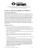
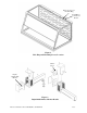
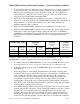
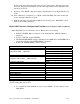
2. First remove the large 1.19" dia. gray hole plug. See Figure 1. See Figure 2 only to
reference internal assembly of the airflow monitor. Locate the elbow, locknut, and washer
and install it in the 1.19" dia. hole per Figure 1 and Figure 2. The enclosure baffle pivots
down to install the elbow, washer and locknut.
3. Cut the 1" hose supplied with the kit to 10.5" approximate length and install it between the
airflow sensor and the elbow.
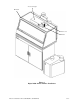
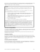
4. Secure the Guardian Digital alarm to the enclosure with double stick tape as shown in
Figure 3. The airway passage between the alarm module and the enclosure is now
complete.
5. Locate the metal hose cover and install with double stick tape per Figure 3. (Omit this step
on the Protector Work Stations.)
6. Locate the power supply transformer. One end should already be connected to the two-
pin connector labeled 15 VDC on the back of the alarm module and through the strain
relief bushing. If disconnected, then reconnect to power the airflow monitor. Plug the
115V power supply into a standard 115V duplex receptacle, the back of the accessory
FilterMate portable exhauster or the back of the accessory light. For 230V, plug into a
standard receptacle with your specific outlet plug. (It is recommended that the airflow
monitor be connected directly to the FilterMate switched auxiliary outlet so the
airflow monitor is powered at the same time.)
7. Installation is now complete.