User’s Manual Open Combination (Macro) Kjeldahl Systems Models 21232 Series 21233 Series 21236 Series 21237 Series To receive important product updates, complete your product registration card online at register.labconco.com Labconco Corporation 8811 Prospect Avenue Kansas City, MO 64132-2696 800-821-5525, 816-333-8811 FAX 816-363-0130 E-MAIL labconco@labconco.com HOME PAGE www.labconco.com Please read the User’s Manual before operating the equipment.
Copyright © 2010 Labconco Corporation. All rights reserved. The information contained in this manual and the accompanying products are copyrighted and all rights reserved by Labconco Corporation. Labconco Corporation reserves the right to make periodic design changes without obligation to notify any person or entity of such change. Warranty Labconco provides a warranty on all parts and factory workmanship.
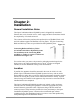
TABLE OF CONTENTS CHAPTER 1: INTRODUCTION Components Shipped General Description Performance Component Identification 1 1 2 3 3 CHAPTER 2: INSTALLATION General Installation Notes Location Electrical Tap Water Supply Distillation Manifold Water Aspirator Exhaust System Acid Fume Blower Exhaust System Blower Airflow Exhaust Volume Requirement & Velocity Test Digestion Rack Drip Shield Glassware Installation 6 6 6 7 8 8 9 11 11 12 13 CHAPTER 3: NORMAL OPERATION & ROUTINE MAINTENANCE Normal Operation Start-
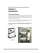
Chapter 1: Introduction Components Shipped Carefully check the contents of your Open Combination Kjeldahl System for shipping damage while it is still on the shipping pallet. Do not discard the packaging material until the contents have been checked and the equipment has been approved for installation. The Open Combination Kjeldahl Nitrogen System has been shipped in one complete crate to minimize damage that may occur in transit.
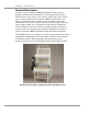
Chapter 1: Introduction General Description Labconco’s Open Combination (Macro) Kjeldahl Nitrogen System is designed to facilitate the determination of Total Nitrogen content within materials such as feeds, grains, soils, fertilizers, plant tissue, water, organic wastes, and food products. The expression ‘Macro’ identifies the size of sample vessel and the sample size that can be used with this equipment.
Chapter 1: Introduction Performance The Open Combination Kjeldahl Digestion and Distillation Systems have been designed for use in the determination of nitrogen (or ammonia) concentrations. By calculation nitrogen can be converted to protein values for products such as plant tissues, meats and other food substances. Nitrogen determinations with the Open Combination (Macro) Kjeldahl Systems can accommodate sample sizes up to 5 grams due to the size of the digestion/distillation flasks.
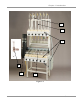
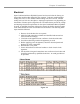
Chapter 1: Introduction 3. Acid Fume Blower Exhaust System. Located on the left side of the unit, this blower removes excess sulfuric acid fumes from the digestion flasks. The blower is direct-drive with corrosion resistant impeller wheel. The blower draws the sulfuric acid fumes through the CPVC digestion manifold and discharges the fumes under positive pressure out through a duct work system connected to the buildings exterior.
Chapter 1: Introduction 5 6 1 4 3 2 Figure 1-2 Product Service 1-800-522-7658 5
Chapter 2: Installation General Installation Notes The Open Combination Macro-Kjeldahl System is shipped fully assembled. Exhaust duct work, electrical service, water supply and drain connections should be completed by a licensed contractor. The customer will need to purchase their preferred size of Kjeldahl Flasks, with one-hole-rubber-stoppers and distillate receiving flasks. The glass Connecting Bulbs and Delivery Tubes are provided with each Kjeldahl System.
Chapter 2: Installation Electrical Open Combination Macro-Kjeldahl Systems have been wired at the factory per the product model number ordered by the customer. Labconco model numbers ending in 01 are 115 volts. Model number ending in 02 are 230 volts. Models ending in 03 are 230 volt, three phase. Amperage requirements vary depending on the number of heaters per the digestion rack. The tables below provide the voltage and amperage electrical requirements for the Open Combination Macro-Kjeldahl Systems.
Chapter 2: Installation Tap Water Supply NOTE: ALL PLUMBING CONNECTIONS AND COMPONENTS MUST BE FREE OF FOREIGN MATERIAL BEFORE FINAL CONNECTIONS ARE MADE. Distillation Manifold The Open Combination Macro-Kjeldahl Systems feature an upper distillation rack with individual condensation columns, these are connected together by a common manifold (6 columns per manifold).
Chapter 2: Installation Water Aspirator Exhaust System Figure 2-4 For models with a Water Aspirator For correct operation, the water aspirator’s 3/4" NPT connection must be connected to a 3/4" supply line with a minimum of 60 psi line pressure. The water aspirator system is sized for use with a nominal 3" dia. line. The aspirator discharge pipe terminates with a 3" dia. PVC coupling to drain and a 11/2" dia., 45° vent coupling for connection to an air roof vent.
Chapter 2: Installation Water Aspirator Acid Fume Removal System Figure 2-5 Do not locate trap directly below water ejector stub, or water may backup into the air vent and stop the fume removal through your exhaust manifold.
Chapter 2: Installation Acid Fume Blower Exhaust System The exhaust duct connection on top of the blower is sized for use with 6" nominal (6-5/8" O.D.) vent duct. The blower assembly is supplied with a short piece of 6" PVC pipe and a flexible coupling with clamps to connect the blower housing assembly to the duct work exhaust stack.
Chapter 2: Installation (Duct Area in Square Feet) x (Average Airflow Velocity in feet per minute) = (Air Volume CFM) (Pi) radius² X 117 FPM = 25 CFM The exhaust stack rising from the blower exhaust connection must be vented to the outside atmosphere. A 6" diameter duct is sufficient for carrying the fumes a distance not exceeding 60 feet. In estimating the duct length count each 90° elbow as 12 feet and add to the straight length total of duct for the duct system.
Chapter 2: Installation Glassware Installation Connecting Bulb Rubber Tubing Distillation Manifold Delivery Tube Distillation Flask Receiving Flask Figure 2-8 Product Service 1-800-522-7658 13
Chapter 3: Normal Operation & Routine Maintenance Normal Operation Start-Up 1. The KNA apparatus is designed for use with either 500 or 800-ml Kjeldahl Flasks. The digestion heaters are free to move forward or backward on the runway to accommodate either size flask. 2. Turn the heat controllers to the setting on both the Digester and Distillation racks if both racks will be used simultaneously. Wait approximately 5 to 10 minutes to insure proper preheating.
Chapter 3: Normal Operation & Routine Maintenance Clean-Up and Cosmetic Guidelines • • • Keeping the Open Macro Kjeldahl System clean will preserve the appearance and improve life of the equipment. The equipment can be kept clean by washing with a weak solution of sodium hydroxide and rinsing with clear water. Sulphate, a salt of Sulfuric Acid, may build up between the channel support and the fume removal manifold.
Chapter 3: Normal Operation & Routine Maintenance Drip Shield The drip shield is constructed of stainless steel and is resistant to most acid attack. Acid spills can however cause discoloration and eventual marring of the surface unless the following proper procedures are followed in their clean up. 1. Promptly wash down all major acid spills contained by the shield. 2. Periodically clean the stainless surface with any residential stainless steel sink cleaning compound. 3.
Appendix A: Replacement Parts Electrical Heaters and Motor/Blower Parts Part Number Description 1315400 1315500 2011500 2023200 2033100 2033200 2023100 2031800 1870200 1317100 1850500 2053900 1200000 1203200 1203600 1851800 2054500 1451300 2056600 2055400 2055500 1851100 2053000 1967000 2144600 1662200 2165800 1880128 2164000 Heater Control, Infinite (115Volts) Heater Control, Infinite (230Volts) Core Plate Casting, (package of 6) Heater Base Casting (electric or gas) Heater element, 115V, 600 W, (packag
Appendix A: Replacement Parts Miscellaneous Replacement Parts Part Number 1620500 2152402 2038800 2038900 2031700 2146400 2081300 2128800 2078800 18 Description Tubing, rubber condenser connecting, per foot Distillation manifold – 6 place stainless steel Wire, No 14 Black, SEWF-2, 30 ft length Wire No.
Appendix B: Dimensions & Airflow Requirements B-1 Product Service 1-800-522-7658 19
Appendix C: Total Kjeldahl Nitrogen Method Titrimetric Determination Various scientific associations offer approved Kjeldahl methods. These methods are available at their websites.
Appendix C: Total Kjeldahl Nitrogen Method distillate receiving vessels, such as 250 ml Erlenmeyer flasks. The equipment is available as a combined system, featuring both digestion and distillation apparatus. The preheated burners should bring 250 ml of water at 25° C to a rolling boil with in 5 minutes. Condensation columns should cool distillate to 75° F (23.8°C). 3.3. Titration Class A Burets, 25-50 ml. for dispensing Standardized Acid solution. 3.4. Analytical balance, sensitive to 0.0001grams. 4.
Appendix C: Total Kjeldahl Nitrogen Method the flask neck on the fume removal system. If necessary lower the burner heat setting to prevent sample from foaming up into neck of flask. Once, the sample comes to a smooth rolling boil return heat setting to maximum. When digestion sample clears (no black specs with pale green tint color), continue to boil for an equal length of time as required to reach the clear point, (total time approx. 1 hr).
Appendix C: Total Kjeldahl Nitrogen Method 7. Titration 7.1. Depending on the samples expected nitrogen level and the sensitivity of the titration desired, select the appropriate standardized H2SO4 solution (0.02 or 0.10 normal). High or low nitrogen concentrations will require standardized H2SO4 solutions with stronger or weaker normalitys. Titrations should require at least 15 ml of titrant to be accurate. Fill a class A. buret to the zero line with the standardized H2SO4 solution.
Appendix C: Total Kjeldahl Nitrogen Method Distillation: Excess base is added to the digestion product to convert NH4 to NH3 as indicated in the following equation. The NH3 is recovered by distilling the reaction product. ammonium ammonia heat sulfate gas (NH4)2SO4 + 2NaOH → 2NH3 + Na2SO4 + 2H2O Titration quantifies the amount of ammonia in the receiving solution. The amount of nitrogen in a sample can be calculated from the quantified amount of ammonia ion in the receiving solution.