Glassware Washer Service/Technical Manual SteamScrubber® & FlaskScrubber® Glassware Washers Models 44003 Series 44004 Series 44203 Series 44204 Series FlaskScrubber® Vantage® Series Glassware Washers Model 4540031 Labconco Corporation 8811 Prospect Avenue Kansas City, MO 64132-2696 800-821-5525, 816-333-8811 FAX 816-363-0130 E-MAIL labconco@labconco.com HOME PAGE www.labconco.
Labconco SteamScrubber®, FlaskScrubber®, and FlaskScrubber® Vantage® Model Glassware Washers Table of Contents Introductory Notes . . . . . . . . . . . . . . . . . . . . . . . . i Labconco Service Support . . . . . . . . . . . . . . . . . . . . .ii Glassware Washer Warranty. . . . . . . . . . . . . . . . . . . . iii Section I (Navigating the Washers) . . . . . . . . . . . . . . . .
Drain System Replacement/Installation Replacing the Door Fan Gasket Replacement 54 57 58 Section V (Testing Procedures) . . . . . . . . . . . . . . . . . .60 115/230V SteamScrubber® and FlaskScrubber® 60 230V FlaskScrubber® Vantage® 64 Section VI (Wiring Schematics) . . . . . . . . . . . . . . . . . .68 115V SteamScrubber® and FlaskScrubber® 69 230V SteamScrubber® and FlaskScrubber® 70 208/230V FlaskScrubber® Vantage® 71 Section VII (Parts). . . . . . . . . . . . . . . . . . . . . . . .
Labconco Glassware Washer Service/Technical Manual Introductory Note The Labconco Glassware Washers were re-engineered in 2007, with the new line available in September 2007. The new generation of Glassware Washers include updated features and modifications that set itself apart from the previous generations.
Labconco Glassware Washer Service/Technical Manual Labconco Service Support Labconco prides itself on the personal touch it gives to supporting our products. The customer and the product are supported by several departments. At anytime, any of these departments can be contacted to provide additional support. For inquiries regarding the application of each washer and accessories, contact the Marketing Department’s Product Specialist/Manager.
Labconco Glassware Washer Service/Technical Manual Copyright © 2008 Labconco Corporation. All rights reserved. The information contained in this manual and the accompanying products are copyrighted and all rights reserved by Labconco Corporation. Labconco Corporation reserves the right to make periodic design changes without obligation to notify any person or entity of such change. Warranty Labconco provides a warranty on all parts and factory workmanship.
Labconco Glassware Washer Service/Technical Manual SECTION I: Navigating the New Labconco Glassware Washers This section will familiarize you with the functions needed to perform various services on the washers. This includes running diagnostic tests, and a general landscape of the interior of the washer (pictures included). Washer Menus The latch serves as the on/off switch for the washer. When the latch is closed (to the right) the machine will come on.
Labconco Glassware Washer Service/Technical Manual are additional program selections that will be shown on the display if the ▼ button is pressed. If an arrow is visible in the upper right corner of the display, additional program selections will be displayed when the ▲ button is pressed. 5. Press RUN if no modifications to the program are necessary. 6.
Labconco Glassware Washer Service/Technical Manual Running the diagnostics test 1. Press the ▲ button on the control panel, close the door and slide the door latch to the right. Hold for 5 seconds. 2. The display will show the Diagnostics screen and the indicator on the left side will point to TAP WATER VALVE. 3. Press either the ► or ◄ button to turn the tap water valve ON. Tap water should enter the washer. Allow water to enter for approximately 1 minute.
Labconco Glassware Washer Service/Technical Manual 20. Press the ▼ button and the arrow on the display will point to COOL FAN. 21. Press either the ► or ◄ button, and the small fan inside the kick panel will operate. 22. This completes the check of most of the washer functions. Unlatch the door to exit from the Diagnostics mode. 23. To verify the proper operation of the overfill switch, repeat steps 1 & 2 above.
Labconco Glassware Washer Service/Technical Manual Inlet Solenoid Valves (Blue) Top (rear) Left Electrically controlled to allow water to fill the tank of the machine. DI/Pure Water Pump (Pink) Bottom(front) Left Integrated pump to allow the use of a non-pressurized Pure water source. Wash Pump/Motor (Yellow) Top (rear) Right The pump has been moved away from the sump in order to minimize the occurrences of motors being damaged by leaks.
Labconco Glassware Washer Service/Technical Manual Removing the Toe/Kick Panels & Service Panels (Under-Counter Models) For many cleaning, maintenance and repair jobs associated with the FlaskScrubber® and/or SteamScrubber®, the toe & kick panels will need to be removed. This will help gain access to parts inside the base of the washer and is necessary for initial install of the machine. Remove the Toe/Kick Panel 1. Remove the two screws located at the bottom of the panel. 2.
Labconco Glassware Washer Service/Technical Manual Removing the Washer Top, Back, and Side Panels (Free-Standing models only) To gain access to internal parts of the washer you will need to remove the washer’s top, back, and side panels. This will make it possible to clean, maintain, and repair the washer. Refer to the figure below and follow the instructions to remove the top, back, and side panels of your washer. To Remove the Cosmetic paneling of the Washer 1.
Labconco Glassware Washer Service/Technical Manual SECTION II: Maintaining and Modifying the Glassware Washers Like any piece of laboratory equipment, the glassware washer requires some routine maintenance and, depending on the laboratory’s function, some modification. Section II contains instructions on how to perform upkeep and application driven changes.
Labconco Glassware Washer Service/Technical Manual Maintaining the Water Fill Valve The filter screen of the water fill valve, illustrated below, may require periodic cleaning to remove trapped particles. A low water fill occurs if the blockage is not removed. To Clean the Water fill valve 1. Turn off the water and electrical power to the washer. Unplug the Mobile model; turn off the circuit breaker that services the UnderCounter or Freestanding model. 2. Remove the rear panel of Free-Standing models. 3.
Labconco Glassware Washer Service/Technical Manual * Debris that falls into the sump can damage and/or destroy the wash and drain pumps. To Replace the Filter Screen If the filter screen is damaged or too dirty to clean and needs to be replaced follow the instructions above to remove the original filter screen and keep the hardware. Once removed, position the new screen and insert the holding screw in place. Make sure that the 1/8” drilled hole is located below the water distribution channel.
Labconco Glassware Washer Service/Technical Manual Adjusting the Door Latch Keeper Strike Plate If, when the door is closed and latched, the latch is loose, or the machine turns off during a cycle due to vibration or bumping, then you may need to adjust the Door Latch Keeper/Strike Plate. Adjusting the Door Latch Keeper/Strike Plate 1. Open the door to the glassware washer. 2. Loosen the two screws indicated by the Red Arrows. 3.
Labconco Glassware Washer Service/Technical Manual To replace the washer light bulb 1. Turn off electrical power to the Glassware Washer. 2. Remove the lower and middle panels as described in Removing the toe/kick panels. 3. Disconnect the springs on each side that connect the pivot brackets to the washer base. Disconnect the hook on the washer base side. 4. Remove the two screws on each side of the outer door panel. Lower the panel and remove it. 5.
Labconco Glassware Washer Service/Technical Manual To replace the conductivity sensor 1. Turn off the electrical power to the washer. Turn off the circuit breaker that services the washer. 2. Remove the cabinet back panel. 3. Unplug the sensor from the wiring harness. 4. Unscrew the sensor from the sump housing. 5. Reverse this procedure when installing a new sensor. Note: When replacing the sensor, use Teflon Tape on pipe threading.
Labconco Glassware Washer Service/Technical Manual Modifications Installing (FlaskScrubber®) & Adjusting the Upper Rack The Upper Rack comes standard on the SteamScrubber®; however, the FlaskScrubber® has the option of adding the Upper Rack (Spindle or Basket). The Optional Upper Spindle Rack provides 30 additional spindles for washing narrow-neck glassware and is customizable by removing spindles or by installing Multi-Pin Inserts. The Open Basket allows for the washing of open mouthed glassware.
Labconco Glassware Washer Service/Technical Manual * To synchronize the travel of the slides, attach the upper rack and pull it all the way out gently. Pull the rack out firmly several times to the maximum travel length. When you push the rack in, the door should close easily and latch smoothly. Washing Tall Glassware / Removing Upper Rack When the Upper Rack is in place, it limits the height of the glassware that can be washed. If very tall glassware or long pipets are to be washed, remove the Upper Rack.
Labconco Glassware Washer Service/Technical Manual Installing Optional Pipet Inserts Two sizes of Pipet Inserts are available. The 8-place Pipet Insert accommodates 1 mL to 10 mL pipets. Multiple Pipet Inserts may be installed, if desired. To install an 8-place Pipet Insert (Below Left): 1. Insert the tool supplied with the Spindle Rack or a screwdriver into the top of a spindle and turn counterclockwise to remove the spindle. 2.
Labconco Glassware Washer Service/Technical Manual To install a 16-place Pipet Insert (Above Right): 1. Use the tool supplied with the Spindle Rack or a screwdriver to remove the six spindles on either the front or rear of the spindle rack. Remove others if necessary. 2. Replace the left and right spindles with the two short spindles that you received with the Pipet Insert. 3. Replace all other spindles with the plastic plugs that you received with your washer. 4.
Labconco Glassware Washer Service/Technical Manual 6. Replace the back paneling. 7. Attach the hose from the valve to a Twin Inlet High Flow Air-gap suitable for dishwasher applications. This may be obtained from a plumbing supply store. 8. Attach the drain hose from the Glassware Washer to the other inlet of the Air-gap. 9. Attach the Air-gap to the building drain. And turn back on the electrical power.
Labconco Glassware Washer Service/Technical Manual 7. 8. 9. 10. 11. 12. 13. Remove the lower panel and the electrical junction box cover as described in Removing the toe/kick panel. Plug the supplied harness into terminal J6 on the Relay PCB and route the other end to the left rear corner of the washer base. Plug the wire from the detergent container to the mating connector in the new harness in the base of the washer.
Labconco Glassware Washer Service/Technical Manual SECTION III: Troubleshooting and Alarms To be effective in properly servicing laboratory equipment, it is essential to be able to troubleshoot any problem and gain a clear and concise root to the problem to accurately correct the problem. This section is split into two sections. The first is a chart dealing with Basic Troubleshooting for a wide range of issues.
Labconco Glassware Washer Service/Technical Manual (49°C). Insufficient wash Time Increase wash cycle time. Insufficient water Check to be sure the water shut-off valve is fully open. Check to be sure the water pressure is between 20 and 120 psi (138-827 kPa) at a flow rate of 1.25 gallons per minute (4.7 liters/minute). Check water level switch. Clogged filter Clean sump filter. Drain line clogged or kinked Disconnect drain line and clean or remove kink.
Labconco Glassware Washer Service/Technical Manual Obstruction in drain Line Remove obstruction. Washer overfilling Check operation of fill switch. Improper installation Unit not level Check cabinet opening to see if it is aligned properly with the door. Washer must be level. Adjust feet to level unit. Adjust feet to level unit. Door opened during operation Allow 4-5 seconds before opening door after unlatching. Clogged drain Clean out drain.
Labconco Glassware Washer Service/Technical Manual Conductivity reading “0” Sensor not connected Reconnect sensor wires. Sensor defective Replace sensor. Sensor dirty Clean sensor. Conductivity Reading fluctuates Washing action cause Bubbles None. Temp Reading Stuck or Fluctuating at 16ºC Poor Connection between Sensor and PC Board Check Connectors between Temp Sensor and Sensor Wiring Harness. Inspect integrity of Sensor Wiring Harness.
Labconco Glassware Washer Service/Technical Manual Hose from washer must not be attached to another hose. Check for kinks in hose. Drain hose must not be elevated more than 30 inches. Pump lost its prime Remove ALL water from inside drain hose. Pump will prime when water drains from washer. Building plumbing defective Check for blocked air gap. Filter screen clogged Clean screen in bottom of washer. Defective fill level Switch Contact Labconco Product Service.
Labconco Glassware Washer Service/Technical Manual Check Connectors between Ribbon Cable and PC Board. Water Low Alarm Faulty Temperature Sensor Temp Sensor Bad. Improper water supply Make sure water is turned on. Replace. Tap water pressure must be at least 20 psi (138 kPa) and flow must be at least 1.25 gallons (4.7 liters)/minute. DI water supply must have flow of at least 0.9 gallons (3.4 liter)/minute. At least 3.4 gallons (13 liters) must be available for each DI rinse.
Labconco Glassware Washer Service/Technical Manual Low Temp Alarm Heater inoperative Check electrical connections. Check voltage to heater. Check resistance of heater. If open circuit, replace heater. Defective controller Check output from PCB to heater. Replace PCB. Contact Labconco Product Service. Defective temperature probe Defective high temperature cut out switch Check electrical connections. Contact Labconco Product Service. Replace if necessary. Check resistance of safety cut out switch.
Labconco Glassware Washer Service/Technical Manual drain water that is in the washer. The alarm is canceled by opening the door. LIQ DETER This displays if the level of the detergent in the dispense container is low. The alarm is disabled if the detergent dispense volume is set to “0.” The alarm is canceled when detergent is added to the container. RINSE AID This displays if the level of the rinse aid solution in the dispenser container is low.
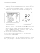
Labconco Glassware Washer Service/Technical Manual Figure 1: Above Left: Interior Door: Door with window. Circle A indicates location of door latching mechanism and power switch to be triggered for override. Above Right: Door Switch Override: The red circle shows the rectangular hole in the inside top of the door where the door switch can be triggered for going through prescribed diagnostic tests with the door open. The Blue Arrow is pointing to the Door Latch.
Labconco Glassware Washer Service/Technical Manual 2. Disconnect feed tube from valves and inlets (NOTE: depending on when the alarm went off, it could be either the hot tap water valve or the DI) 3. Inspect fill valve for blockages or sticking solenoid valve plunger. 4. Test electrical functionality of valve. 5. inspect hoses for blockages 6. Replace the valve if it will not open, or if it has no resistance across the two terminals. 7.
Labconco Glassware Washer Service/Technical Manual close to the water distribution tower as possible. Be careful not to drill through the plastic sump underneath the screen. The drilled hole is a shortterm solution. If this must be done, contact Product Services at 1(800)821-5525 to get a replacement screen from the manufacturer.
Labconco Glassware Washer Service/Technical Manual Fig 3 (above left): Looking down on the back of a unit, with the Service Panel removed. (A) Overflow Sensor. (B) Pure Water Valve. (C) Hot Tap Valve. Fig 4 (above right): Looking through the service panel area, the Overflow Sensor (A) is bolted to a stud on the base of the unit with two red connectors with grey leads coming off of it.
Labconco Glassware Washer Service/Technical Manual 8) With the wash pump ON, use a flashlight and inspect all hoses, clamps and fittings for leaks. Be sure to also inspect the fittings at the water inlet valves (Fig 3b & 3c) 9) If no leaks are found with wash pump running, proceed to Diagnostic Drain. a. Scroll down (▼) to “Drain/cool” and push ◄ or ► until the screen says "yes". b. Observe as before for leaks. NOTE: Correct any and all leaks as appropriate with power off to the machine. c.
Labconco Glassware Washer Service/Technical Manual 2. 3. 4. 5. 6. 7. Press and hold the ▼ button and close the handle of the washer by sliding the door latch knob to the right. Hold for 5 seconds. The display will show the SET UP screen. The > on the left side will highlight VOLTAGE. Press the ▼ button until the > highlights LIQ DETERGENT OPT Press the ◄ or ► buttons to select “NO” and turn off the PC Boards detergent level sensor.
Labconco Glassware Washer Service/Technical Manual ______________ Verify that the Water Temp to the unit from the start is 120ºF or GREATER for every fill. ______________ To service the Drain System, Remove the front Toe Kick Panel & Side Panel. CHECK VALVE & PUMP Figure 7: (left) Drain Valve. (A) Valve Actuator Lever. (B) Electrical Connector Leads. Figure 8: (below) Front View of Drain Pump. (C) Drain Pump Inlet. (D) Drain Pump Impeller. (E) Drain Pump Motor. (F) Drain Pump Fan.
Labconco Glassware Washer Service/Technical Manual 8. 9. 10. 11. 12. 13. 14. After wash 1 fill, open door and verify water level. Shut door and resume cycle. At wash 1 drain (wash1=4 minutes) verify valve is opening, you will hear a click and the lever on top of valve will move [fig. 7A]. (Look in the left side) After 3 seconds verify drain pump comes on. You can see the motor fan [fig. 8F & 9I] turning located under the electrical box, lower right side mounted to base. Time the Drain.
Labconco Glassware Washer Service/Technical Manual Figure 10 Below: Drain Hose Routing. (V) Drain hose at Drain Pump. (W) Drain hose OVER Wash pump Hose. (X) Wash Pump. (Y) Zip Tie holding the Drain Hose to the outside of the Wash pump (on the housing boss). Right: Drain hose high loop. (Z) Zip Ties holding the loop in place. Notice that the top of the loop goes up to the ledge of the back panel. Loop MUST be in place to prime the pump.
Labconco Glassware Washer Service/Technical Manual Figure 11 Above: Fill Trap Switch. Fill Switch has replaced traditional Float Switch in the new style Steam & Flask Scrubber Glassware Washers. Fill Switch may be referred to as the “pressure switch”. Right: Fill Trap Switch Assembly System. (K) Fill Trap Switch. (L) Black and Orange electrical wiring. (M) Fill Switch Pressure Hose. Hose is to be replaced if electrical check shows that the switch is open.
Labconco Glassware Washer Service/Technical Manual Checking the function of the Sump Heater 1. Remove the front paneling as described in “Removing the Toe/Kick Panels” in Section I. 2. Locate the power supply cords and place an Ammeter around the power supply wiring. 3. Go to Diagnostics (as described in “Accessing the Diagnostic Mode” in Section I) and use the ▼ button until “HEATER” is highlighted. Press ◄ or ► button and the heater will be energized. 4.
Labconco Glassware Washer Service/Technical Manual Figure 13 Above Left: Back of washer Temperature Probe (B) connection to the Base Wiring Harness (C). Above Right: With the Toe, kick and Relay Board Cover panels removed, find the relay board on the bottom front left of the machine. The Base Wiring Harness connects to this board at Circle D. 3. Remove the front paneling as described in “Removing the Toe/Kick Panels” in Section I. 4.
Labconco Glassware Washer Service/Technical Manual SECTION IV: Part Replacement Once the root cause of a failure has been determined, it may be time to replace parts. When major part replacement of the various washer systems is required, use this section’s various procedures for assistance. Replacing the PC Board, Display Panel and Button Pad The PC (timer) Board, Display Panel and Button Pad are all part of the Control Module Interface.
Labconco Glassware Washer Service/Technical Manual Replacing the PC Board 1. Remove the Control Module from Control Panel. 2. Remove the four screws holding the display panel onto the Control Module. 3. Pull the Display Panel to disconnect the pins from the PC Board and remove it. 4. Disconnect the pin connector of the button pad from the PC Board. 5. Disconnect the pin connector of the ribbon cable that runs up the door. 6.
Labconco Glassware Washer Service/Technical Manual CAUTION: The voltage selected (115V or 230V) does not change the acceptable AC mains voltage that can be connected to the washer. It only selects the programs that are suitable for the identified voltage. 5. Press the ▼ button and TEMP UNITS will highlight. 6. Press ◄ or ► buttons to select either °F or °C which will be used on the display to set and monitor temperature. 7. Press the ▼ button and DI PUMP ENABLE will highlight. 8.
Labconco Glassware Washer Service/Technical Manual 1. 2. 3. 4. 5. 6. 7. 8. 9. Remove the Control Panel from the door. Access the Control Module as described above and remove it. Disconnect the Button Pad’s ribbon cable from the PC Board. Pull the Button Pad Sticker from the Control Panel and discard. Fit the ribbon cable of the new Button Pad through the slot in the Control Panel. Center and Place the Button Pad sticker on the Control Panel.
Labconco Glassware Washer Service/Technical Manual 7. Use diagnostics to check fill times and function of the new valve. 8. Re-install the panels. Figure 17 Above Left: Inlet Solenoid Valves (HOT Tap and PURE). The Yellow Arrows point to the mounting screws of the PURE water valve while the Green Arrows point to the mounting screws of the HOT tap water Valve. The screws are mounted with lock nuts from behind. Above Right: Inlet Solenoid Valves with Hoses and Clamps.
Labconco Glassware Washer Service/Technical Manual 7. Use diagnostics to check fill times and function of the new valve. 8. Re-install the panels. DI/Pure Water Pump Replacement Use the following procedures to replace/install the DI/Pure Water Pump. This pump allows the user to supply the washer with nonpressurized, gravity-fed purified water. The pump works in conjunction with the DI/Pure Water solenoid valve to fill the washer when set to use Purified water (during rinses).
Labconco Glassware Washer Service/Technical Manual contact (Overfill) is actuated then the washer will stop and display an “Overfill Alarm”. If the first contact isn’t actuated in time (3 min for tap, 5 min for DI/Pure) the washer will stop and display a “Low Water Alarm”. See the Troubleshooting section for further details. **Completely drain and disconnect electrical power to the unit before proceeding with any of these instructions. Replacing the Pressure Switch 1.
Labconco Glassware Washer Service/Technical Manual 13. If the unit doesn’t pass or alarms, follow the troubleshooting section for that alarm. Replacing the Pressure Switch Hose 1. Pull the unit away from the wall so that you have access to the backside of the washer. 2. Remove the cosmetic back panel or the back service access panel. 3. Pull the black insulation jacket up and secure it. 4. Locate the Pressure Switch Hose. (Fig 20) 5. Loosen the clamp and remove the hose from the Sump connection. 6.
Labconco Glassware Washer Service/Technical Manual **Completely drain and disconnect electrical power to the unit before proceeding with any of these instructions. 1. 2. 3. 4. Pull the unit away from it’s installation space. Remove the back and right cosmetic panels or service access panels and pull up the black insulation jacket and secure it. Locate the Wash pump in the back right corner of the machine. Loosen the clamps holding the two hoses to the pump connections and remove the hoses from the pump.
Labconco Glassware Washer Service/Technical Manual 11. Test the unit in diagnostics. Replacing the Wash Arms The wash arms are responsible for distributing the water throughout the tank and ‘scrubbing’ the glassware clean. If they become deteriorated or clogged or need to be replaced for any other reason, follow the instructions below for their replacement. **Completely drain and disconnect electrical power to the unit before proceeding with any of these instructions. 1.
Labconco Glassware Washer Service/Technical Manual **Completely drain and disconnect electrical power to the unit before proceeding with any of these instructions. 1. 2. 3. 4. 5. Open the Washer’s door and remove the screws that hold the door’s outer cosmetic panel in place. To remove the panel, pull down slightly as you pull away from the door to dislodge it. Locate the Detergent Cup. Disconnect the Cup’s wires from the Door Wiring Harness.
Labconco Glassware Washer Service/Technical Manual Figure 25 Left: Sump Screen (before the Water Distribution Channel has been connected). The Red Arrow shows the single screw that holds the sump screen down to the sump below. This must be pulled out to remove the Sump Screen. The Green Arrow points to the 1/8” hole drilled in the sump screen that is designed to break hard water’s surface tension without allowing large shards of glass, debris, or rogue labware from getting into the sump.
Labconco Glassware Washer Service/Technical Manual 4. Loosen and remove nuts on the underside of the tank that hold the sump in place. 5. Open the door of the washer and remove any racks inside the tank. 6. Locate the element clamps. 7. Using a screw driver, loosen the jaws of the clamps. 8. Pull the Element up and out of the tank. 9. Replace the new element, tighten the clamp jaws and secure with the original nuts and attach the wiring connections. (The Seal Washers are to be replaced when the heater is.
Labconco Glassware Washer Service/Technical Manual 1. 2. 3. Pull the unit away from walls/cabinets so that you have access to the back and left sides of the washer. Remove the back and left cosmetic panels or service access panels and pull up the black insulation jacket and secure it. Locate the Blower mounted to the floor of the base weldment. Figure 27 Right: FlaskScrubber ® Blower.
Labconco Glassware Washer Service/Technical Manual Figure 28 Left: FlaskScrubber® Vantage® Blower. Just like the Blower in the FlaskScrubber® the blower (indicated by the Yellow Bracket) is held to the base weldment by a mounting Bracket, Magenta Bracket. The Green Arrow shows the clamp that holds the flexible ducting that leads to the manifold, to the Blower. The Red Arrow points to the clamp that secures the Flex Ducting that comes from the HEPA filter in the left Side Cabinet to the Vantage's® Blower.
Labconco Glassware Washer Service/Technical Manual the unit has a BLUE 230V valve and the unit is running on 208V, call Labconco for the Engineering Upgrade (Gold valve). 1. Remove the right side service panel (or right side Panel if Free Standing) and the Toe/Kick Panels. See Removing the Toe/Kick Panels and Service Panels and/or Removing the Washer’s Paneling. 2. Locate the Drain Solenoid valve. 3. Loosen and remove the hose clamp on the “Drain Pump Inlet Tube” at the Drain Pump.
Labconco Glassware Washer Service/Technical Manual 7. 8. 9. Seat the new drain valve over the studs in the base weldment. Tighten down the nuts that secure the Drain Pump to the base weldment. Place the pump side of the “Drain Pump Inlet Tube” on the Drain Pump and tighten the clamp. 10. Using a compressed air source, eliminate the water from the drain tube or remove it from the drain plumbing and drain it out all the way before connecting it to the new pump. 11.
Labconco Glassware Washer Service/Technical Manual Figure 31 Right: Drain Hose back High Loop. After the Drain Hose exits the base of the unit, it arches up into a high loop where it clamped and zip tied to the outer shell of the tank. This loop holds the water used to prime the pump for each drain sequence. The Blue Arrows indicate the direction that water flows when the Drain Pump is on. The water leaving the sump goes up the right side of the loop (facing the back of the machine) and down the left side.
Labconco Glassware Washer Service/Technical Manual 7. Position the new door fan at the holes, making sure the air flow is correct (out), and then insert the holding screws. 8. Connect the wires from the door fan to the Wiring Harness. 9. Reconnect/turn on power to the unit. 10. Using Diagnostics check the function of the Door “cooling” fan. Gasket Replacement Door Removal Before the two gaskets (baffle gasket and door gasket) can be removed and replaced the washer’s door must be removed. 1.
Labconco Glassware Washer Service/Technical Manual Baffle Gasket Remove the damaged gasket (fig 2D) by pulling it from its housing at the tank’s baffle (fig 3H). The unit may or may not have clips holding the two gaskets into place (fig 1B). If it DOES, then those clips will need to be removed, saved, and reinstalled when the new gasket is put into place. 1. Remove the clips and the silicon holding the gasket into place at the baffle/water deflector. 2.
Labconco Glassware Washer Service/Technical Manual SECTION V: Testing Procedures For Reference Purposes this manual includes Labconco’s testing procedures. These are the same documents used for testing the units’ quality as they come off the manufacturing line. There are two Testing Procedures; one for the 115V and 230V SteamScrubber® and FlaskScrubber®, and one for the FlaskScrubber® Vantage®. 115/230V SteamScrubber® and FlaskScrubber® FINAL INSPECTION PROCEDURE FOR STEAMSCRUBBER AND FLASKSCRUBBER Rev.
Glassware Washer/Test Report MODEL NUMBER VOLTS/HZ M.O. NUMBER SERIAL NUMBER INSP/TESTS Set-Up No. 1 2 3 4 5 6 7 CONDITIONS AND REQUIREMENTS Connect tap and pure water. Connect drain. Connect proper electrical power. (Use 115V, 60 Hz or 230V, 50 Hz) Connect current probe to power line. Close detergent cup door Connect computer via RS232 Set up washer control A. Open door B. Press and hold ▼ button- Simultaneously close and latch door. C. Press ▼ button to select function.
INSP/TESTS Run Test No. 1 2 3 4 5 62 CONDITIONS AND REQUIREMENTS 230 V 115 V DETERGENT CUP HEATER 9.3 – 11.5 Amp 7.8 – 9.6 Amp Return to TAP – Allow water to fill washer until it turns off. Press and hold RUN – Water must turn off before it overflows. DRAIN / COOL – Allow all water to drain DRY BLOWER LIQ DETERG PUMP (No test) LIGHT (Window models only) FAN INST/LCC# Ammeter Visual Visual Audible Visual Aubile Fill Detergent Cup with Detergent.
INSP/TESTS No. CONDITIONS AND REQUIREMENTS Hi-Pot 1 1000V for 1 minute. Final 1 2 3 4 5 6 Check for Leaks Unit must be Clean and Dry All parts in place in good condition Verify that thermostat on back of tank is installed properly. Make sure drain hose is routed over top of wash pump.
230V FlaskScrubber® Vantage® INSPECTION PROCEDURE FOR VANTAGE GLASSWARE WASHER Rev. A B C 64 Date 5/8/07 7/16/07 8/2/07 12/21/07 By LLK LLK LLK DKT Description Release Added Overfill Test Clarified Verbiage No Change to Tests Dry temp tol. Was +/- 5 deg.
Glassware Washer/Test Report MODEL NUMBER VOLTS/HZ M.O. NUMBER SERIAL NUMBER INSP/TECH/ INSP/TESTS Set-Up No. 1 2 3 4 5 6 7 8 CONDITIONS AND REQUIREMENTS Connect tap and pure water. Connect drain. Connect electrical power. (230V, 50 Hz) Connect current probe to power line. Close detergent cup door Connect computer via RS232 Connect test dispense bottles to the detergent & acid supply lines. Set up washer control A. Open door B. Press and hold ▼ button- Simultaneously close and latch door. C.
INSP/TESTS No. CONDITIONS AND REQUIREMENTS partially wetted. Top of heater must be partially unwetted. Close door and resume DIAGNOSTICS WASH PUMP DETERGENT CUP HEATER 7.8 - 9.6 Amp Return to TAP – Allow water to fill washer until it turns off. Press and hold RUN – Water must turn off before it overflows. DRAIN / COOL – Allow all water to drain DRY BLOWER LIQ DETERG PUMP .1 - .2 Amp LIGHT FAN RINSE AID PUMP .1 - .
5 Wash 1, Steam, Rinses 1 & 2, Dry Time +/- 1 minute Wash 2, Final Rinse Time after reaching SP +/- 1 minute Conductivity varies between 100 - 1200 Confirm operation of low detergent and acid rinse monitor Detergent Dispense 18 - 22 ml Rinse Aid Dispense 5 - 7 ml Observe Wash Action – Water hits top of tank from spindles INSP/TESTS No. 6 CONDITIONS AND REQUIREMENTS Run rinse only to wet surfaces. After wash pump starts, place a wet towel across the overflow contacts.
SECTION VI: Wiring Schematics Each unit comes with a built-in Wiring Schematic/Diagram. This diagram can be found on the internal side of the door’s outer skin panel. There is not one included in the User’s Instructional Manual. For the purposes of Electrical Troubleshooting, all three Wiring Schematics have been included in this Service Manual.
Labconco Glassware Washer Service/Technical Manual 115 Volt FlaskScrubber® and SteamScrubber® 69
Labconco Glassware Washer Service/Technical Manual 230 Volt FlaskScrubber® & SteamScrubber® 70
Labconco Glassware Washer Service/Technical Manual 208/230 Volt FlaskScrubber® Vantage® 71
Labconco Glassware Washer Service/Technical Manual SECTION VII: Parts List The parts list included in this section is not all inclusive, but contains a rather cumulative list of parts needed for any service and maintenance. If there is ever any question about parts and part numbers, contact Labconco Product Services at 1(800)821-5525, at labconco@labconco.com, or www.labconco.com.
Labconco Glassware Washer Service/Technical Manual 45415-00 Clamp, Blower to mount (FS) 45277-00 Duct Reducer, 3” to 2” (FS) 19686-00 Clamp, Motor Blower to 3”(FS) 16245-01 Hose, 3” (Motor Blower)(FS) 19676-00 Clamp, Reducer to 2” (FS) 16245-00 Hose, 2” from Blower (FS) 45881-00 Relay Board Assy 45880-00 Pump Inlet Elbow 45869-00 Drain Valve, 115V 45869-01 Drain Valve, 230V 45867-00 DI Fill Valve, 115V 45867-01 DI Fill Valve, 230V 45859-00 I/O Sensor Cable 45853-00 Main Wiring Harness 45843-00 Drain Pump 1
Labconco Glassware Washer Service/Technical Manual Accessories 45956-00 Upper Spindle Rack 45845-00 Slides 45712-01 Wash Arm Assy (Middle) 45958-00 Upper Spindle Rack (w/o Slides) 45712-01 Wash Arm Assy (Middle) 44942-00 8 Place Pipet Washer 1-10 mL 44775-00 Very Short Spindles 45952-00 16 Place Pipet Washer 1-50 mL 44246-00 Glassware Holder (Tulip) Small 44248-00 Glassware Holder (Tulip) Large 45960-00 Small Spindles w/ Clips 45957-00 Lower Spindle Rack 45918-01 Spindle – Long 45918-00 Spindle – Short 440
Labconco Glassware Washer Service/Technical Manual New Style Washer Conversion Parts: Under Counter to Free Standing Cat # Description Qty 45891-00 45891-01 45893-00P 45894-00* 45975-00 18981-12 18983-06 44680-00 19302-00 Right Panel Left Panel Back Panel Top Panel Panel Spacer Screw Screw Plug Nut 1 1 1 1 4 14 12 2 2 46038-00** Conversion Kit 1 *Top Panel is required when adding any combination of the back or side paneling.