IN STRUC TION MANUA L Laboratory Equipment Pty Ltd email: sales@labec.com.au Ph: 02 9560 2811 • Fax: 02 9560 6131 www.labec.com.
OPERATION MANUAL H2G-0 HOMOGENIZER PLEASE READ THE MANUAL CAREFULLY BEFORE USE.
I. OUTLINE SPEED DISPLAY MOTOR POWER SWITCH (ON THE BACKSIDE OF THE BODY) SPEED ADJUSTER POLE HOMOGENIZER HEAD UNIT HIGH-LOW ADJUSTER RING FOR HIGHT FIXING PURPOSE STAND BASE II.
III. 1. OPERATION INSTRUCTION It should keep at least 1 cm of the distance between the tip of the stirring shaft and the inside bottom of the vessel. Don’t let the homogenizer head touch to the bottom of the vessel. 2. Rotate the speed adjuster knob toward the left end; then plug in the power cord and switch the machine on. 3. Press “START” button and adjust to the desired speed; press “STOP” button to stop the stirring. 4.
IV. CAUTION 1. Avoid using this machine with other instruments in one and same power supply. 2. Serious or often overloaded use should be possible to cause the fast carbon brush consumption as well as the motor damage. 3. It’s necessary to turn to a low speed for 1~2 hours at least after changing a new carbon brush, otherwise the motor will be damaged possibly. 4. The speed has to match material’s viscosity to avoid head at empty rotation. 5.
VI. APPLICATION OF HEADS Model K-7S Applicable range To homogenize or mix on cell tissue in micro volume. 1. To disperse plant or animal tissue. 2. To treat suspensions and emulsions. K-12S 3. Homogenizing and mixing. 4. Extraction function. 1. To disperse plant or animal tissue. 2. To treat suspensions and emulsions. K-20S 3. Homogenizing and mixing. 4. Extraction function. 1. To disperse organic and inorganic matters. K-30 VII. 2. Homogenizing and mixing. 3. Extraction function.
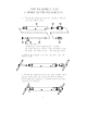
VIII. ASSEMBLING & DISMANTLING K-7S, 12S, 20S AND K-30 STEPS FOR ASSEMBLING K-7S (* REVERSE THE STEPS FOR DISMANTLING) 1. Follow the diagram to put all the parts orderly into the connect pipe. 4 1 2 3 5 6 Each part name: (1) Bolt (2) Inner shaft of connect pipe (3) Pad (4) Connect pipe (5) Pipe (6) Turning cutter 2. Follow the diagram to insert the tools into the connect pipe. 3. Follow the diagram to turn the tools toward their correct directions for fixing the whole assembly.
STEPS FOR ASSEMBLING K-12S (* REVERSE THE STEPS FOR DISMANTLING) 1. Follow the diagram to put all the parts orderly into the connect pipe. 6 1 3 2 4 5 7 Each part name: (1) Bearing (2) E-typed washer (3) Bolt (4) Inner shaft of connect pipe (5) Pipe (6) Connect pipe (7) Turning cutter 2. Follow the diagram to insert the tools into the connect pipe. 3. Follow the diagram to turn the tools toward their correct directions for fixing the whole assembly.
STEPS FOR ASSEMBLING K-20S (* REVERSE THE STEPS FOR DISMANTLING) 1. Follow the diagram to put all the parts orderly into the connect pipe. 5 1 3 2 6 4 7 8 Each part name: (1) Bearing (2) E-typed washer (3) Bolt (4) Inner shaft of connect pipe (5) Connect pipe (6) Pipe (7) Fixed cutter (8) Turning cutter 2. Follow the diagram to insert the tools into the connect pipe. 3. Follow the diagram to turn the tools toward their correct directions for fixing the whole assembly.
STEPS FOR ASSEMBLING K-30 (* REVERSE THE STEPS FOR DISMANTLING) 1. Follow the diagram to put all the parts orderly into the connect pipe. 5 1 3 2 6 4 8 7 9 Each part name: (1) Bearing (2) E-typed washer (3) Bolt (4) Inner shaft of connect pipe (5) Connect pipe (6) Pipe (7) Fixed cutter (8) Inner pipe (9) Outer pipe (10) Turning cutter 2. Follow the diagram to insert the tools into the connect pipe. 3.
IX. ERROR MESSAGES Signal Status Description Repairing 1. Motor can not drive 1. Bad carbon brush touch 1. Check the carbon brush. 2. Wire matched badly. 2. Check the wiring. 3. The controller is out of order. 3. Replace a new controller. 2. Motor stops during 1. Bad carbon brush touch 1. Check the carbon brush or 2. Wire matched badly. replace a new one. 3. The controller is out of order. 2. Check the wiring. 3. Replace a new controller. Err-1 running 1. Check the speed sensor or 3.
DI SP LA Y FUSE 10 1 Power switch Co nt ro l boa rd G ND AC IN VR 1 1 TEMP S W MOTOR SPEED SENSOR Co nt ro l Po we r P. C. 1 X.