Prism™ Microcentrifuge User Manual C2400 C2400-100V C2400-230V C2500 C2500-100V C2500-230V Lit M00029 Rev 2 December 2012
Safety Precautions NEVER use the centrifuge in any manner not specified in these instructions. NEVER operate the centrifuge without a rotor properly attached to the shaft. NEVER tighten rotor nut by hand only. NEVER fill tubes while they are in the rotor. Liquid spillage may harm unit. NEVER put hands in the rotor area unless the rotor is completely stopped. NEVER move the centrifuge while the rotor is spinning. NEVER use solvents or flammables near this or other electrical equipment.
Table of Contents 1. General Information Description Safety precautions Technical data Accessories supplied with unit Warranty 1 2. Installation Unpacking the centrifuge Required space Installing the centrifuge 2 3. Installation of rotor ad rotor maintenance Rotors and accessories Rotor maintenance Removing and installing the angle rotor Loading the rotor Overloading rotors 3 4.
1. General Information This manual provides important safety information for the Prism microcentrifuge. It should be kept near the centrifuge for quick and easy reference. 1.1 Description The Prism is a small benchtop centrifuge designed for separation of various research samples. The motor is brushless and requires no routine maintenance. The Prism is supplied with a 24 x 1.5/2.0ml rotor for micro sample tubes. Adapters are available for tubes smaller than 1.5ml.
1.3 Technical data Dimensions Width Depth Height 9.45 inches 13.8 inches 7.48 inches Maximum speed 15,000rpm Maximum RCF 21,200 x g Maximum volume 24 x 2.2ml Admissible sample density 1.2kg/dm3 Electrical/fuse rating 120V~, 50-60Hz, . A, 5 AT 230V~, 50-60Hz, 1. A, 2.5 AT Operating temp./humidity 0ºC to 40ºC / ≤80%RH 1.4 Accessories supplied with centrifuge Each unit is supplied with 1 instruction manual, 1 warranty card 1 power cord, a standard angle rotor and a rotor removal tool. 1.
2.2 Required space The centrifuge should be installed on a rigid, even surface such as a stable laboratory bench, countertop, etc. To guarantee sufficient ventilation, ensure that the centrifuge has at least 15cm (6 inches) of free space on all sides, including the rear. The centrifuge should not be located in areas subject to excessive heat such as in direct sunlight or near radiators or the exhaust of a compressor, as a buildup of heat may occur within the chamber. 2.
Adapter for 0.5ml tubes (pk./6) Order no. C-1205 Tube measurement 8 x 30mm Max. speed 15,000rpm Centrifuging radius 7.53cm RCF (g-value) 18,942 x g Adapter for 0.4ml tubes (pk./6) Order no. C-1206 Tube measurement 6 x 47mm Max. speed 15,000rpm Centrifuging radius 8.4cm RCF (g-value) 21,200 x g Adapter for 0.2ml tubes (pk./6) Order no. C-1222 Tube measurement 6 x 21mm Max. speed 15,000rpm Centrifuging radius 7.03cm RCF (g-value) 17,684 x g 3.
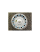
Figure 1.
To replace rotor, first make sure the motor shaft and rotor mounting hole are clean. Place the rotor on the motor shaft. Reinstall the rotor securing screw on the motor shaft by turning it clockwise. Hold the rotor with one hand and tighten the rotor securing screw, using the rotor wrench. 3.4 Loading the rotor Tubes to be loaded should be filled equally by eye. The difference in the weight between the tubes should not exceed 0.1 gram.
4. Operation ATTENTION: Never attempt to operate the centrifuge with rotors or adapters that show signs of corrosion or mechanical damage. Never centrifuge strongly corrosive materials that may damage the rotors, accessories, or bowl of the unit. 4.1 Attaching rotor lid After the rotor has been properly secured and loaded, attach the rotor lid to the rotor. Always use the rotor lid for safety and to allow the rotor to reach proper speed.
display shows “--” which indicates continuous run. In this mode, the centrifuge will run until manually stopped. To start a run, press the control knob. When the preselected time expires, the centrifuge will stop automatically. To stop the centrifuge prior to the expiration of set time, press the control knob. The centrifuge may be operated for a short run by pressing and holding the control knob.
5.3 Cleaning the rotor The rotor should be cleaned after each use. When spinning samples containing phenol or phenol chloroform, the rotor should be cleaned immediately after use. 5.4 Disinfection Should a spill of infectious materials occur within the rotor or chamber, the unit should be disinfected. This should be performed by qualified personnel with proper protective equipment. 5.5 Replacing fuses Check the fuse when it is recommended in the Troubleshooting Guide located in this manual.
Centrifuge cannot be started, although power is on Possible reason: Solution Lid not closed correctly Close lid correctly Possible reason: Solution: No speed or time has been selected Set speed and/or time bAL: Error Message Possible reason: Solution: Possible reason: Solution: Indicates imbalance Tubes not inserted symmetrically in rotor holes Load tubes symmetrically (see Section 3.
7. Where to call Should you have any questions about the Prism or its accessories, please call your local Labnet distributor or Labnet’s USA Customer Service Department at 732 417-0700. Customer Service is staffed from 8:30am to 5:30pm, EST, Monday through Friday. Our 24 hour fax number is 732 417-1750. Inquiries may also be sent via our electronic mailbox at labnetinfo@corning.com. Should your Prism require service, please call Labnet’s Technical Services Department at 732 417-0700.
APPENDIX Symbols and Conventions The following chart is an illustrated glossary of the symbols that may be used in this manual or on the product. The electrical warning indicates the presence of a potential hazard which could result in electrical shock. CAUTION This symbol refers you to important operating and maintenance (servicing) instructions within the product Instruction Manual. Failure to heed this information may present a risk of damage or injury to persons or equipment.
To use this chart, find the radius value on the radius scale. Place the edge of a ruler on the value. Place the right side edge of the ruler on the speed scale at the desired speed. The estimated RCF can then be read from the RCF scale where the ruler edge passes through it. This chart can also be used to determine the proper speed for the desired RCF value.
Declaration of Conformity Number: CE 000FM Manufacturer: Labnet International, Inc,., 31 Mayfield Ave., Edison, NJ 08837 USA Labnet International declares that the devices described below are in conformity with the EC directives listed. In the event of unauthorized modification of any of the devices listed below, this declaration becomes invalid.
LIMITED WARRANTY Labnet International, Inc. warrants that this product will be free from defects in material and workmanship for a period of one (1) year from date of purchase. This warranty is valid only if the product is used for its intended purpose and within the guidelines specified in the supplied instruction manual. Should this product require service, contact Labnet International, Inc.’s Service department at 732-417-0700 to receive a return authorization number and shipping instructions.