
User's Manual


4
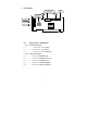
2.2. Audio Connectors Pin Assignment:
L: LEFT CHANNEL SIGNAL
G: GROUND
R: RIGHT CHANNEL SIGNAL
L: LEFT CHANNEL SIGNAL
G: GROUND
R: RIGHT CHANNEL SIGNAL
R G G L
R G L G
1:
PHONE IN
2,3 : GROUND
4:
MONO OUT
J10 (CD
-IN)
J11(CD
-IN)
J13 (TAD/Voice Modem)
J20 SPDIF OUT
1: SPDIF OUT
1
2
3
4
2.GROUND
3 Installing the Sound Card
1. Power off the system and all peripheral devices. Unplug all power cords from the
power utility outlets.
2. Momentarily touch the chassis of the system unit with your bare hand to discharge
any static electricity.
3. Remove the cover from the system unit.