
User Manual


ESS Audio/Modem Combo Card
Page - 4
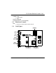
1.5. Connectors and Jumper
This Combo Card includes four external Jack Ports, and one external TELEPHONE/LINE
Connector, and two internal connectors.
1.5.1. External Connectors:
J1:............................ φ 3.5mm Phone Jack for TELEPHONE
φ 3.5mm Line Jack for LINE/WALL
J2:............................ φ 3.5mm Phone Jack for MIC IN
J4:............................ φ 3.5mm Phone Jack for LINE IN
J5:............................ φ 3.5mm Phone Jack for AUDIO OUT
J6:............................ Connector for MIDI/JOYSTICK
1.5.2. Internal Connectors:
J3:............................ Internal Connector for CD-IN (JST)
JP1:.......................... Internal Connector for SPDIF (JST)
2. HARDWARE INSTALLATION
2.1. Handling the Combo Card
WARNING: Static electricity can damage your equipment. Do not take the card out of
its static protective bag until you are ready to work with it.
Follow these precautions when handling the board:
Before you open the static protective bag, touch it to a metal expansion slot cover on the
back of your computer. This drains static electricity from the package and from your
body.
Do not touch any exposed printed circuitry after opening the package.
Keep other people from touching the board. They might have a static-electricity build-up.
Limit your movement. Movement causes a build-up of static electricity.
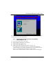
2.2. Installing the Combo Card
Step 1. Turn off the system and all peripheral devices.
Step 2. Disconnect the power cord and all peripheral devices from the system.
Step 3. Remove the system cover and identify an unused PCI slot.
Step 4. Unscrew the slot cover plate, plug in the Combo Card, and tighten it with
the screw.
Step 5. Plug the telephone cable of the PHONE Jack J1 into the Jack on the back
of your telephone.