
Operation Manual


INSTALLER’S MANUAL
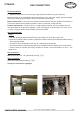
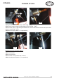
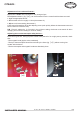
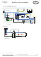
For references and descriptions of the various components refer to table 9 in appendix 0
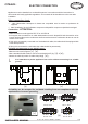
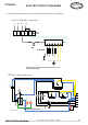
Note: Ignition controller terminal lugs not in use
are to be grounded.
LG1531G (Gas hob + 1 gas oven)
SFE530 (1 static electric oven)
N2
N1
L3
L2
L1
X1
Q
°
P2
P1
P3
2
1
3
4
5
2
1
3
4
5
H
H1
TH
KM
T1
L1
T2
L2 13
14T3
L3
KM
T1
L1
T2
L2 13
14T3
L3
TL2
32 31
22 21
12 11
32 31
22 21
12 11
R3
R3
R1A
A1
A2
A1
A2
KM2
H
SCE1_020
S
ELECTRIC CIRCUIT DIAGRAMS
Ft 144a - GB - Rév 02 - Modifié le : 08/09/08 19/44
CITEAUX :