
Operation Manual


INSTALLER’S MANUAL
N2N1
L3L2L1
LE
SB
2
S
P1
H
RV1
Simple
3 1
4
P3 P1 P2
2 1 3 45
Crd
H
S2
RV2
Double
24
4A
P1 P2 Pilot
4A 4 2
S1
S2
S
H
Crd
H
2
S
P1
H
RV1 ’
Simple
3 1
4
P3 P1 P2
2 1 3 45
Crd
H
S2
RV2 ’
Double
24
4A
P1 P2 Pilot
4A 4 2
S1
S2
S
H
Crd
H
N2N1
L3L2L1
N2N1
L3L2L1
LE
2
S
P1
H
RV1
Simple
3 1
4
P3 P1 P2
2 1 3 45
H
2
S
P1
H
2
S
P1
H
RV1
3 1
4
P3 P1 P2
2 1 3 45
P3 P1 P2
2 1 3 45 2 1 3 45
RV2
Double
24
4A
P1 P2 Pilot
4A 4 2
S1
S2
S
H
S
RV2
24
4A
P1 P2 Pilot
4A 4 2
S1
S2
S
H
2
S
P1
H
RV1 ’
Simple
3 1
4
P3 P1 P2
2 1 3 45
SB
2
S
P1
H
2
S
P1
H
RV1
3 1
4
P3 P1 P2
2 1 3 45
P3 P1 P2
2 1 3 45 2 1 3 45
RV2 ’
Double
24
4A
P1 P2 Pilot
4A 4 2
S1
S2
S
H
RV2
24
4A
P1 P2 Pilot
4A 4 2
S1
S2
S
H
R4
R4
KM
P2
P1
P3
2
1
3
4
5
2
1
3
4
5
Q°
TH
M
M
S
H1
H
R1A
TL2
32 31
22 21
12 11
32 31
22 21
12 11
A2
KM2
A1
A2
A1
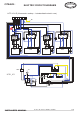
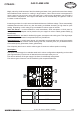
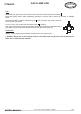
SCE1_032
LVTR 1541 CT (Vitroceramic cooktop + 1 fan-assisted electric oven)
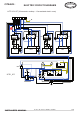
ELECTRIC CIRCUIT DIAGRAMS
Ft 144a - GB - Rév 02 - Modifié le : 08/09/08 22/44
CITEAUX :