0" WET TILE/STONE SAW www.Lackmond.com Instruction Manual BEAST10 To reduce risk of serious injury, thoroughly read and comply with all warnings and instructions in this manual and on product.
TABLE OF CONTENTS TECHNICAL SPECIFICATIONS ................................................ 2 MAKING CUTS ........................................................................14 GENERAL SAFETY INSTRUCTIONS ....................................... 3 MAINTENANCE ....................................................................... 16 SPECIFIC SAFETY INSTRUCTIONS FOR TILE SAW ............... 5 SAW FEATURES ........................................................................7 UNPACKING THE SAW ......
.,5,9(3 :(-,;@ 05:;9<*;065: ), :<9, [V YLHK HUK \UKLYZ[HUK HSS PUZ[Y\J[PVUZ PU [OPZ THU\HS ILMVYL \ZPUN [OPZ >L[ ;PSL :[VUL :H^ -HPS\YL [V MVSSV^ HSS PUZ[Y\J[PVUZ TH` YLZ\S[ PU LSLJ[YPJ ZOVJR MPYL HUK VY ZLYPV\Z WLYZVUHS PUQ\Y` :VTL K\Z[ JYLH[LK I` \ZPUN WV^LY [VVSZ JVU[HPUZ JOLTPJHSZ RUV^U [V [OL Z[H[L VM *HSPMVYUPH [V JH\ZL JHUJLY HUK IPY[O KLMLJ[Z VY V[OLY YLWYVK\J[P]L OHYT :HML[` PZ H JVTIPUH[PVU VM \ZPUN JVTTVU ZLUZL Z[H`PUN HSLY[ HUK RUV^PUN OV^ `V\Y [PSL ZH^ ^VYRZ 9LHK [OP
.,5,9(3 :(-,;@ 9<3,: ;()3, $PSHUH UDWLQJ a 9ROWV IW IW IW $ : * 9a a 7RWDO OHQJWK RI FRUG LQ IHHW IW a a QRW UHFRPPHQGHG .96<5+05.
GENERAL SAFETY RULES TOOL SAFETY s KEEP ALL GUARDS IN PLACE and in working order. s AVOID ACCIDENTAL STARTING. Be sure the switch is in the “Off” position before plugging the tool into an electrical outlet. s DO NOT CARRY TOOLS WITH YOUR FINGER ON THE SWITCH. s DO NOT OVER REACH. Keep proper footing and balance at all times. s DO NOT FORCE THE TOOL. Use the correct tool and cutting wheel for your application.
:7,*0-0* :(-,;@ 05:;9<*;065: -69 >,; ;03, :;65, :(> JVU[ $OORZLQJ GXVW WR JHW LQWR \RXU PRXWK RU H\HV RU WR OLH RQ WKH VNLQ PD\ SURPRWH DEVRUSWLRQ RI KDUPIXO FKHPLFDOV 7LOH 6DZ -PN 8VH RI DFFHVVRULHV WKDW DUH QRW UHFRPPHQGHG IRU XVH ZLWK WKLV WRRO PD\ FUHDWH KD]DUGRXV FRQGLWLRQV 3RZHU 6XSSO\ &RUG 8VH RI DFFHVVRULHV WKDW DUH QRW UHFRPPHQGHG IRU XVH ZLWK WKLV WRRO PD\ FUHDWH KD]DUGRXV FRQGLWLRQV ÷ +09,*;065 6- -,,+! $OZD\V IHHG ZRUN LQWR WKH &XWWLQJ ZKHHO DJDLQVW WKH
SAW FEATURES ;OL WHY[ UHTLZ HUK WHY[ U\TILYZ JVYYLZWVUK [V [OVZL \ZLK PU [OL (ZZLTIS` 6WLYH[PVUZ HUK 4HPU[LUHUJL ZLJ[PVUZ VM [OPZ THU\HS 1. Main frame Inset 2. Lower splash tray 15. Water hose 3. Upper splash tray 16. Bevel lock knob 17. Height Adjustment Knob & Wing Locknut 18. Depth of cut lock knob 4. Anti-splash guard 5. Motor/arm assembly 6. Blade guard 7. On/Off switch 8. Blade 9. Worktable 17 18 10. Miter guide 11. Water tray 12. Table extension 13.
UNPACKING Compare package contents to Component Parts List and Hardware Package List prior to assembly to make sure all items are present. Carefully inspect parts to make sure no damage occurred during shipping. If any parts are missing, damaged or preassembled, do not assemble. Instead, call Service Center at 1-800-850-2044 for assistance. Prior to tool assembly and use, read this manual thoroughly to familiarize yourself with proper assembly, maintenance and safety procedures.
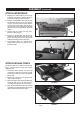
(::,4)3@ 7KH SDUW DQG KDUGZDUH QDPHV DQG QXPEHUV FRUUHVSRQG WR WKRVH XVHG LQ 6DZ )HDWXUHV RQ SDJH DQG WKH 6KLSSLQJ &RQWHQWV RQ SDJH 05:,9; ;/, >(;,9 ;9(@ (QVXUH WKH VDZ LV RQ D OHYHO DQG VWDEOH VXUIDFH WKDW ZLOO VXSSRUW ZHLJKW RI VDZ WUD\ DQG FRQWHQWV ÷ 11 6HH )LJXUH ,QVHUW ZDWHU WUD\ E\ VOLGLQJ LW LQWR WKH IUDPH DV VKRZQ 7KH OLS RI WKH WUD\ VKRXOG UHVW RQ WRS RI WKH OHIW DQG ULJKW UDLOV RI WKH PDLQ IUDPH ,I XVLQJ ZLWK D VWDWLRQDU\ RU SRUWDEOH VWDQG ÷ 7K
ASSEMBLY (continued) ATTACH WORKTABLE 1. Position the slotted table lock (A, Fig. 8) in the open position so that the groove is parallel to the rails on the main frame. 2. Position the worktable (9) so that the two left bearings (B, Fig. 8) on the bottom engage, one over and one under, with the left rail of the main frame. The wheel on the right side of the worktable should ride along the top of the right rail on the main frame. B A 3. Slowly slide the table onto the rails, pushing it all the way in. 4.
ASSEMBLY (continued) INSTALL TABLE EXTENSION 1. The table extension (12) installs on the right side of the worktable. 2. Position the table extension so that the two pins on the extension line up with the two holes (A, Fig. 12) on the worktable as shown. 3. Engage the pins on the extension with the holes. 4. Secure the extension to the worktable by tightening the thumbscrew (B, Fig. 13) located on the bottom of the extension. A FIGURE 12 B FIGURE 13 ATTACH THE MITER GUIDE 1.
46=05. (5+ :;6905.
OPERATION (continued) TO USE A BUCKET AS A WATER SUPPLY 1. Position a large bucket on the floor and beneath the pump containment area. 2. Place pump (14) in bottom of the bucket. 3. Attach the free end of the water hose into the outlet nipple of the pump. 4. Secure slack hose and power cord to the snap ties provided on the rear of the saw (A, Fig.17). A 5. Fill the bucket completely but do not overfill. 6. Operate the saw as directed in “Making Cuts” (page 14).
OPERATION (continued) RE-SETTING THE SHORT-CIRCUIT SAFETY BUTTON This saw is equipped with a safety feature that prevents the power plug from short-circuiting in case it gets wet. D Whenever the saw’s power plug is disconnected from the power source, the safety feature will trip the internal breaker. This is normal. To start the saw after it has been reconnected to a power source, depress the red reset button (D, Fig. 20) so that it locks in place.
OPERATION (continued) Bevel Cut B The saw enables you to make beveled cuts at 45-degrees and 22.5 degrees. CAUTION: If using the bevel function, the saw must be positioned exactly at 45 or 22.5 degrees as shown on the bevel indicator. Make sure the pointer matches up with the line on the bevel scale. To make a bevel cut: 1. Loosen the bevel lock (A). 2. Tilt the saw head so that the pointer on the saw head aligns with the desired bevel as shown on the bevel indicator (B). 3. Tighten the bevel lock. 4.
MAINTENANCE For your safety, turn off the switch and unplug saw from the power source before performing any maintenance or cleaning. If the power cord becomes damaged in anyway, replace it immediately with the approved cord. When cleaning the saw, do not expose the motor to direct water. If excessive water is introduced into the motor, electric shock and/or damage to the motor can occur. Do not service the electric motor’s internal components yourself. Contact an authorized service center.
MAINTENANCE (continued) CHECKING THE BEVEL 1. Position the worktable (9) so that it is under the blade. 2. Loosen the blade cover lock knob. 3. Swing the blade cover (6) open. 4. With the bevel indicator at 0 degrees, use a framing square to ensure the blade is square with the table. 5. If the blade is not square to the sliding table, adjust the positive stop screw (A) in the direction that the blade needs to move in order to square it to the table. Use a small square to check blade to table squareness. 6.
ADJUSTMENTS Before performing any adjustments, make sure the tool is unplugged from the power supply and the switch is in the OFF position. Failure to heed this warning could result in serious personal injury. This saw has been adjusted at the factory to make accurate cuts. However, should your tile saw need adjustment after it has been unpacked and assembled or due to machine wear, the following steps will be used to align the table to the saw blade.
TROUBLESHOOTING For your safety, turn on/off switch to the OFF position and unplug the saw from the power source before performing any of the trouble shooting steps below. 1. Motor is too hot: • Turn off motor and let it cool down to room temperature • Check and clean ventilation openings • If the above actions do not fix the problem, call the Service Center at 1-800-850-2044. 2.
3065 Chastain Meadows Parkway, Building 200, Suite 200 Marietta, GA 30066 (800) 850-2044 s WWW.LACKMOND.