
Data Sheet


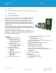


Table Of Contents
- 1 Scope
- 2 Introduction
- 3 Module Variants
- 4 Functional Description
- 5 Block Diagrams
- 6 General characteristics
- 7 Electrical Characteristics
- 8 Pin Definitions
- 9 Power States
- 10 Crystal Oscillator Requirement
- 11 Power-On Signal Timing Diagrams
- 12 Host interface
- 13 Mechanical Specifications
- 14 Soldering Recommendations
- 15 Wi-Fi / Bluetooth MAC ID
- 16 Miscellaneous
- 17 Regulatory
- 18 Ordering information
- 19 Bluetooth SIG Qualification
- 20 Additional Assistance

Sterling™ LWB+
Datasheet
https://www.lairdconnect.com/
9
© Copyright 2022 Laird Connectivity
All Rights Reserved
Americas: +1-800-492-2320
Europe: +44-1628-858-940
Hong Kong: +852-2762-4823
3.3 453-00085 – Chip Antenna module
This module variant integrates the 453-00083 Base SiP Module, a ceramic chip antenna, and all associated RF matching
components on a PCB. This integrated antenna module simplifies and reduces the cost for the host integration of using the
module.
Figure 3: Sterling LWB+ Chip Antenna module (453-00085)
3.4 453-00141 – Module, Sterling LWB+, M.2, Key E, SDIO, UART
This M.2 2230, E-key, SDIO/UART module variant integrates the 453-00083 Base SiP Module, a MHF4 RF connector, and all
associated RF matching components on a PCB. This integrated MHF4 connector, and the M.2 2230 form factor provide an
industrial standard for the host integration when using the module.
Figure 4: Sterling LWB+ M.2 2230, E-key, SDIO/UART module (453-000141)