
Data Sheet


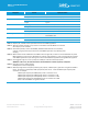
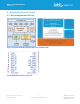

Table Of Contents
- 1 Overview and Key Features
- 1.2 Application Areas
- Features and Benefits
- 2 Specifications
- 3 Hardware Specifications
- 3.1 Block Diagram and Pin-out
- 3.2 Pin Definitions
- 3.3 Electrical Specifications
- 4 Functional Description
- 4.1 Power Management (includes brown-out and power on reset)
- 4.2 Clocks and Timers
- 4.3 RF
- 4.4 UART Interface
- 4.5 SPI Bus
- 4.6 I2C Interface
- 4.7 General Purpose I/O, ADC and PWM/FREQ
- 4.8 nRESET Pin
- 4.9 nAutoRUN Pin
- 4.10 RM1xx VSP Service and Modes
- 4.11 Two-Wire SWD Programming/Debug Interface
- 4.12 RM1xx on-board chip antenna characteristics
- 5 Hardware Integration Suggestions
- 6 Mechanical Details
- 7 Application Note for Surface Mount Modules
- 8 FCC and IC Regulatory Statements
- 9 CE Regulatory
- 10 EU Declarations of Conformity
- 11 Ordering Information
- 12 Bluetooth SIG Qualification

RM1xx LoRa/BLE Modules
Datasheet
https://connectivity.lairdtech.com/wireless-
modules/lorawan-solutions
8
© Copyright 2019 Laird. All Rights Reserved
Americas: +1-800-492-2320
Europe: +44-1628-858-940
Hong Kong: +852 2923 0610
Categories Feature Implementation
LoRa (External) Dipole antenna with U.FL (IPEX) connector up to 2 dBi
Physical Dimensions 25.4 mm x 25.4 mm x 3.1 mm
Weight 3 grams
Environmental Operating -40 ˚C to +85 ˚C (VCC 1.8V – 3.5 V)
Storage -40 ˚C to +85 ˚C
Miscellaneous Lead Free Lead-free and RoHS compliant
Warranty 1-Year Warranty
Development Tools Development Kit Development Kit DVK-RM1xx and
Free Software Tools
Approvals Bluetooth® SIG Listed – Declaration ID
FCC / IC / CE RM191-SM: FCC/IC, RM186-SM: CE
Note 1: DSR, DTR, RI, and DCD can be implemented in the smart BASIC application.
Note 2: With I2C interface selected, pull-up resistors on I2C SDA and I2C SCL MUST be connected
externally as per I2C standard.
Note 3: SPI interface (master) consists of SPI MOSI, SPI MISO and SPI CLK. SPI CS is created by
customer using any spare SIO pin within their smartBASIC application script allowing multi-
dropping.
Note 4: RM1xx module comes loaded with smart BASIC runtime engine FW, but does not come loaded with any smart
BASIC application script (as that is dependent on customer end application or use). Laird provides many sample
smart BASIC application scripts covering the services listed. Additional applications being added every quarter.
Note 5: Laird suggests using Vcc of 3.3V +/-5% (3.13V-3.46V) for maximum LoRa output power.
WARNING: above 3.5V, the LoRa transmitter will be disabled to maintain regulatory compliance
Note 6: Deep Sleep current <750nA (typical).
Standby Doze current 4.2uA (typical).
Note 7: PWM output signal has a frequency and duty cycle property. PWM output is generated using 32-bit hardware
timers. The timers are clocked by a 1MHz (1uS period) clock source. Trade-off PWM output frequency with
resolution. For example:
PWM output frequency of 500kHz (2uS) results in resolution of 1:2
PWM output frequency of 100kHz (10uS) results in resolution of 1:10
PWM output frequency of 10kHz (100uS) results in resolution of 1:100
PWM output frequency of 1kHz(1000uS) results in resolution of 1:1000
Refer to the smartBASIC user guide for details.