
User's Manual

12/2003, CATTRON-THEIMEG
™
Page 3 of 6
Radio Frequency (RF) Transceiver.
Depending upon the System Operating Frequency, the RCR 'Gold Box' may incorporate a 220 MHz or
a R3HNX (450 MHz band) Transceiver Board.
The Transceiver Board is a multi channel, synthesized RF receiver with a Liquid Crystal Display
(LCD). Additionally, it has a built in RF transmitter for ‘POLLING
™
’ data transmission. The receiver
section incorporates a microprocessor and uses Digital Signal Processing (DSP) techniques to
selectively recover digital messages using CATTRON-THEIMEG
™
protocol. The receiver section also
has LED indicators for:
• Power ON
• Carrier Detect (RF signal or carrier is present)
• VCO Lock (receiver locked on freq.)
• Data (received message data)
• Q-sync (synchronization pulse)
The RF Power Amplifier Board is a high power RF amplifier that connects between the R3HNX
Transceiver Board and the Antenna Connector. An on-board LED indicator shows when transmitted
digital RF ‘POLLING
™
’ data from the transmitter section is being amplified and sent to the RCT. Note
that systems operating in the 220 MHz Band do not require this board.
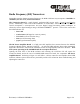
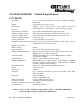
Opening the front door of the RCR enclosure and removing the 'Gold Box' lid will expose the
Transceiver Board, and in the case of a R3HNX MHz transceiver board, the ‘companion’ RF Power
Amplifier Board. Referring to Figure 1-1 and Table 1-1 below, transceiver and amplifier board LED
indicators indicate system status and are particularly useful to the technician when troubleshooting and
adjusting the transceiver.