
User's Manual

Page 4 of 6 12/2003, CATTRON-THEIMEG
™
MP 96 GII LCU [RCR] – Functional Description.
Radio Frequency (RF) Transceiver, continued.
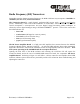
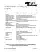
Figure 1-1. Transceiver & RF Amplifier Board LED Indicators
R3HNX (450 Mz)
TRANSCEIVER
BOARD
H
RF AMPLIFIER
BOARD
220 Mz TRANSCEIVER
BOARD
H
VCO
LOCK
LED
DATA
LED
Q-SYNC
LED
CARRIER
DETECT
LED
RECEIVER
POWER
LED
VCO
LOCK
LED
DATA
LED
RF
POWER
LED
TO ANT
TO RX
TO TX
Q-SYNC
LED
CARRIER
DETECT
LED
RECEIVER
POWER
LED
Table 1-1. Transceiver & RF Amplifier Board LED Indicators
LED Description
Transceiver Power This red LED indicates the presence of DC power on the transceiver
circuit board.
Carrier Detect The green Carrier Detect LED indicates that the receiver section is
receiving a RF signal.
Data This yellow LED indicates that the received RF message contains data.
Q-Sync This orange LED indicates an interrupt that signifies the computer/
decoder has received a new message.
VCO Lock This red LED (located underneath the EMI/RFI shield on the R3HNX
board) illuminates when the transceiver frequency synthesizer is unable to
lock onto the required frequency.
RF Power LED This red LED (located on the RF amplifier) flashes when the transmitted
digital RF ‘POLLING
™
’ data from the transmitter is being amplified and
sent to the RCT