
User Manual


-11-
Compenser™ Installation Guide
The COMPENSER™ may only be opened by authorized specialized workshops.
The guarantee is void if opened by any other person. If you require service,
please ask your specialized dealer or contact our customer and product support
department.
Preparations
First decide on where to install the COMPENSER™, taking into consideration
the safety criteria, and fitting it as close as possible to the antenna.
Now decide on the connection points for permanent plus (terminal 30, +),
grounding (terminal 31, -) and ignition / switched plus (terminal 15, ignition). The
connection points permanent plus and ignition must be fused here. The
following fuses may be used:
• permanent plus: fuses 2 A to 5 A
• Ignition: fuses 2 A to 5 A
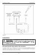
Put out the 3 copper wires, red, brown and blue, with cross-section 0.75 mm².
The 3 wires are assigned as follows:
• red: permanent plus
• brown: ground
• blue: ignition / switched plus lead
You need cable connectors for connecting the 3 copper wires to the equivalent
cables of the car wiring harness.
If the external mobile phone antenna already has an RF-cable, shorten the cable
to the necessary length and crimp an FME cable jack on the open end.
If possible do not use antennas with RF cable RG 174 and suchlike as these lead
to increased losses particularly with GSM 1900.
Have a size 3.2mm drill ready to bore the mounting holes. The last page of this
installation manual shows a drilling template for punch-marking the mounting
holes.
It is important to use the provided cable set to comply
with FCC rules concerning Maximum Permissible
Exposure Safety limits.
The cable between
COMPENSER™ and antenna must be at
least 3.3ft (1m). Please use an omnidirectional 0dBi antenna.