
User Manual


APEX/APEX LT
Datasheet (Preliminary Rev 0.2) www.lsr.com Page 4 of 20
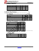
5.4 Receiver
Parameter Min Typ Max Unit
Receiver Sensitivity (1% PER) – normal mode -92 -96 dBm
Receiver Sensitivity (1% PER) – boost mode -93 -97 dBm
Saturation (Maximum Input Level) (1% PER) 0 dBm
802.15.4 Adjacent Channel Rejection
APEX 35 dB
APEX LT 30 dB
802.15.4 Alternate Channel Rejection 40 dB
802.11g Rejection (±10 MHz)
APEX 40 dB
APEX LT 30 dB
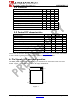
5.5 Control DC characteristics
Parameter Min Typ Max Unit
Logic Input Low 0 0.2VDD V
Logic Input High 0.8VDD VDD V
Logic Output Low 0 0.18VDD V
Logic Output High 0.82VDD VDD V
Output source current (standard pad – APEX) 4 mA
Output sink current (standard pad – APEX) 4 mA
Output source current (high current pad – APEX) 8 mA
Output sink current (high current pad – APEX) 8 mA
I/O pin pull-up and pull-down resistor (APEX) 30
kΩ
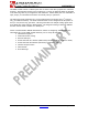
Please refer to the Ember EM250/EM260 datasheets (www.ember.com) for further information
or more details regarding the functional descriptions of the system modules.
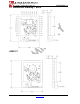
6 Pin Signals, I/O port configuration
The APEX/APEX LT modules have 28 edge I/O interfaces for connection to the user’s host
board. Figure 1 shows the layout of the 28 edge castellations.
Pin 10 Pin 19
Pin 28
Pin 1
Figure 1