
User's Manual


BT85x Series
Datasheet
Embedded Wireless Solutions Support Center:
http://ews-support.lairdtech.com
www.lairdtech.com/bluetooth
7
© Copyright 2017 Laird. All Rights Reserved
Americas: +1-800-492-2320
Europe: +44-1628-858-940
Hong Kong: +852 2923 0610
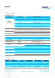
Pin No. Pin Name I/O Supply Domain
Description If Unused
5 USB_D- Bidirectional
3V3 USB data negative N/A
6 GND GND Ground GND
7 NC NC
8 RESET Input 3v3
Active-low reset
input
N/A
9 3v3 Input 3v3
Module main DC
power supply,
Input to internal 1.2V
and 2.5V LDO
N/A
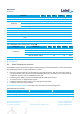
10 NC NC
11 GND GND Ground GND
12 GND GND Ground GND
13 GND GND Ground GND
14 GND GND Ground GND
15 GND GND Ground GND
16 GND GND Ground GND
17 RF
BT850-ST RF signal
output (50Ω)
BT850-SA No
connection
18 GND GND Ground GND
19
I2S_WS/PCM_SYNC
Bidirectional
3V3 PCM sync/I2S word
select
NC
20 I2S_CLK/PCM_CLK Bidirectional
3V3 PCM/I2S clock NC
21 I2S_DI/PCM_IN Bidirectional
3V3 PCM/I2S data input NC
22 I2S_OUT/PCM_OUT
Bidirectional
3V3 PCM/I2S data output
NC
23 NC NC
24 GND GND Ground GND
25
BT_SECI_IN Input 3V3 Coexistence data
input
NC
26
BT_SECI_OUT Output 3V3 Coexistence data
output
NC
27 NC NC
28
GPIO_5 Bidirectional
3V3 Programmable
input/output line
NC
Pin Definition Note:
b
For to meet the pin alignment of BT800, there are several pins which must be put to NC status
(No Connection).
The GPIO_5 controlled by the default firmware for the status of BT850 indications.