
User Manual
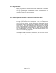
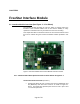
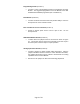
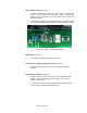
Table Of Contents

Power Supply Circuitry (location 7)
• Location 7 encompasses the power supply circuitry. As shown the
jumper is set for bench power supply (3.5 – 5VDC). Bench power
supply may be connected to the white header (note positive and
negative terminals).
• To use battery supply place the jumper as shown in Figure 3-2 below
and insert 2 AA batteries in power pack onboard the interface board.
Figure 3-2. Jumper Set for Battery Supply
Mode Select (location 8)
• Leave jumpers uninstalled for normal operation
Serial Interface Circuitry and DB9 connector (location 9)
• Onboard host serial interface for use with supplied evaluation
software.
Current Monitor Header (location 10)
• Provides user quick access to monitor current supplied to the RF
Module. Useful in determining current used by device when in
normal or sleep mode.
• To utilize this feature the user must remove the jumper and attach
current monitor between the two header pins.
Page 10 of 39