
User Manual

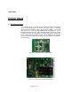
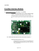
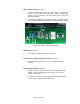
Table Of Contents
Page 9 of 39
Programming Header (location 2)
• Location 2 refers to programming header for programming FreeStar
Module. The suggested programmer for the RF Module is the USB
HCS08/HCS12 Multilink programmer (Part # USB-ML-12)
Reset Button (location 3)
• Location 3 indicates the white button that provides ability to reset the
microprocessor on the FreeStar module.
Port A Header for Access to I/O Pins (location 4)
• Header to provide quick access to Port A pins 4 thru 7 on the
microprocessor.
LED Enable/Disable Header (location 5)
• To utilize LED’s the jumpers must be connected as shown in Figure
3-1. The jumpers may be removed to externally access Port C pin 5
and Port D pins 3 and 4 for input or output operation.
Analog Input Select Header (location 6)
• Location 6 displays 2 yellow variable analog attenuators. With the
jumpers installed as shown in location 6 on the ANALOG I/O header,
the onboard attenuators may be utilized to demonstrate the analog
capabilities of the FreeStar Module.
• Remove the two jumpers to utilize external analog peripherals.