
User Manual


6
2.2 Operational Overview
The quick start demonstration presented in this chapter is referred to as the
ping pong test. The ping pong test allows an end user to easily verify
communication between two transceivers and get a feel for the quality of the
link via feedback of the flashing LEDs.
Operation involves two boards, with one designated as a master device and
the other as a slave device. The master periodically transmits packets to the
slave. If the slave receives and verifies the packet, it will flash its LEDs and
transmit an acknowledgement to the master. If the master receives and
verifies the acknowledgement, it will flash its LEDs.
In normal ping pong mode, LEDs indicate signal strength (two LEDs on
indicate high signal strength, one LED indicates low signal strength). If the
LEDs do not light, the packet or acknowledgement was not received.
2.2.1 Power Up
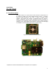
Insert batteries into interface boards and verify that battery supply is selected
using the jumper as shown in Figure 2-3 below (J43 1-2, J18 4-6, J16 5-6,
J16 9-10, and J36 1-2).
Figure 2-3. RF Matrix Module and Interface Board