Nerve Integrity Monitor FC C us e on ly , no t fo rM ed ic al us e NIM Vital ™ Instructions for use
e us al ed ic rM fo no t ly , on e us C FC The information contained in this document is accurate at time of publication. Medtronic reserves the right to make changes to the product described in this manual. Refer to manuals.medtronic.com for the current version. The following are trademarks or registered trademarks of Medtronic in the United States and other countries: NIM Vital™, APS™, Nervassure™, and NerveTrend™.
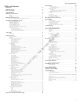
Nerve Integrity Monitor Table of Contents System set‑up Intended use 2 Indications for use 2 Device description 2 Contraindications 2 Warnings and precautions 2 Warnings �������������������������������������������������������������������������������������������������������������������������������������������������������������������������������������������2 Precautions ����������������������������������������������������������������������������������������������������������������������������
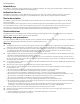
Nerve Integrity Monitor Intended use The NIM Vital is intended for locating and monitoring, including stimulation, of cranial, spinal, peripheral motor and mixed motorsensory nerves and registering EMG responses during surgery. Indications for use The NIM Vital system may be used for EMG monitoring in support of surgical procedures including: intracranial, extracranial, intratemporal, extratemporal and surgeries associated with the neck, spine, thorax, and upper and lower extremities.
Nerve Integrity Monitor FC C us e on ly , no t fo rM ed ic al us e W10 This medical device complies with IEC/EN60601-1-2 safety standard for electromagnetic compatibility, requirements and test. However, if this equipment is operated in the presence of high levels of electromagnetic interference (EMI) or highly sensitive equipment, interference may be encountered and the user should take whatever steps are necessary to eliminate or reduce the source of the interference.
Nerve Integrity Monitor P5 P6 P7 P8 P9 P10 P11 P12 rM fo P15 P16 no t P14 ed ic al us e P13 Avoid accidental contact between ‘PATIENT APPLIED PARTS’ and other conductive parts including those connected to protective earth. The NIM Vital is only compatible with the metal Muting Probe (Ref - 8220325). Earlier model Muting Probes are not compatible. The muting detector is susceptible to damage from dropping. Visually inspect inner jaw surfaces for cracking, chipping or damage prior to use.
Nerve Integrity Monitor 9. Press , or the MONITORING tab to begin monitoring on the Monitoring screen. The NIM Vital system is ready to monitor with its default settings. 10. After the patient is draped, connect a sterile NIM monopolar stimulator probe to the STIM 1 jack (color-coded black plug and black socket). The basics of what you will see and hear during monitoring The following procedure is meant to be completed by surgeons and OR staff users.
Nerve Integrity Monitor Setting up the NIM Vital console 1. Remove the NIM Vital console from its shipping box. 2. Place the console on a stable counter or on the NIM Vital cart (if purchased). Refer to the “Setting up the NIM Vital cart” topic for more information. 3. Install the NIM Vital battery that shipped separately from the NIM Vital system. Refer to the “Installing the NIM Vital battery” topic for more information. 4.
Nerve Integrity Monitor Create a surgeon profile You can create a Surgeon profile from the Select Profile screen. 1. Click [NEW] on the initial setup screen. The New Surgeon Profile dialog box appears. 2. Press the Enter Profile Name text box. The electronic keyboard appears. 3. Type the name of the Surgeon profile. 4. Click [CONFIRM]. The Edit Profile screen appears. 5. Select a procedure(s) from the Available Procedures lists using the tabs to navigate between specialties. 6.
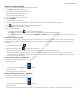
Nerve Integrity Monitor Components Console front 2 Power button. 2 Screen. 3 Camera. 4 Microphone. 4 1 ed ic Console left side al us e 3 1 USB-A (3.0) port. 2 USB-C (3.0) port. fo rM 1 no t 1 FC C us e on ly , 2 1 2 3 4 8 Console right side 1 STIM 1 adjustment knob. 2 STIM 2 adjustment knob. 3 Volume knob. 4 Mute detector adaptor connection.
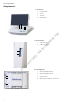
Nerve Integrity Monitor Console screen bottom 1 2 3 5 4 6 1 USB-C. 2 Dual USB-A. 3 Ethernet. 4 Display port. 5 HDMI. Not specifically for use with a microscope. 6 Audio (headphones). Console base back Battery door. 4 Earth ground (P.O.A.G.). 5 Power inlet. 6 Console fuses. C us e on ly , no t fo rM ed ic al 5 Wired patient interface box port. 3 e 6 2 FC 3 4 Patient interface docking cradles.
Nerve Integrity Monitor Patient Interface 13 1 10 2 3 Incrementing Probe Control Jack. Connects Incrementing Probe controls to the NIM Vital. 4 Stimulus (out) Jack, negative (-). 5 Stimulus Return, positive (+). 6 Patient Interface to console connector. 7 The Patient Interface fuses are for Stimulator Output and specifically tested for ECU protection. 8 Positive Electrode Jacks. Positive electrodes have matching color-coded wires and plugs. 9 Negative Electrode Jacks.
Nerve Integrity Monitor to the “Probe-based functions” for additional information on specific button functions. 2 1 1. 2. 3. 4. 3 4 Toggle button normal or at rest. Increase. Decrease. The user can perform the following functions with the toggle button: • Momentary press saves the current screen to memory (for reports) and to a selected peripheral device (printer and/or USB flash drive) if the user selected that option in the settings area.
Nerve Integrity Monitor Screen 2. Select Category 1 2 4 1 Select Procedure Category (if the user selected the default profile on the previous screen). 2 Specialties. 3 Progress tracking bar. 4 Return to previous screen. 1 Go back. 2 Selected category. 3 Select procedure. 4 Progress tracking bar. 3 us no t fo rM ed ic 2 al Screen 3. Select Procedure e 3 1 on ly , 4 FC 2 C us e Screen 4. Connect Devices 4 1 12 5 3 1 Go back to previous setup screen.
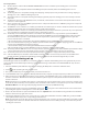
Nerve Integrity Monitor Screen 5. Electrode Check 4 5 6 1 3 7 8 2 10 9 1 Edit Channels. 2 Go back to previous setup screen. 3 Selected procedure. 4 Channel 1 electrode check passed. 5 Channel 2 electrode check failed. 6 Ground check passed. 7 Electrode check show/hide details. 8 Electrode check status bar. 9 Progress Tracking bar. 10 Proceed to monitoring.
Nerve Integrity Monitor Note: If a wireless connection is not available, plug in the patient interface cable between the NIM Vital console and the patient interface. The console connector is located on the back, left side and is marked by a patient interface symbol (refer to the “Buttons and indicators” and “Symbols” topics for more information). 4. Press on the bottom right of the screen. The Check Electrode screen appears and shows the status of the electrode check.
Nerve Integrity Monitor Note: • You can bypass the next place electrodes screen by selecting the MONITORING tab or . • If you bypass the Check Electrode screen, no pre-surgery impedance values of the electrodes, ground, or STIM returns are available for printed/saved reports. • If the patient interface, electrodes, ground, or STIM returns were disconnected when you exit the Check Electrode screen, any printed reports will show a failure of the impedance values of the disconnected item(s).
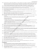
Nerve Integrity Monitor 10 12 11 14 13 9 8 7 15 5 4 6 16 3 17 2 1 1 Scale. Displays screen scale settings. 2 Settings button. 3 Save Profile button (only when settings have been changed, but not saved into a profile). 4 Trace. Display stimulus nerve activity/inactivity. 5 Adjust view. 6 Snapshot button. 7 Freeze button (when activated). 8 Measure button (when activated). 9 Check Electrodes button. 10 Baseline button (only active if the user activates it on the settings panel).
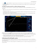
Nerve Integrity Monitor a. Original Rejection Period setting. b. Stimulus Artifact. c. Move Rejection Period line to here to avoid artifact. d. EMG Response. Understanding and recognizing other artifacts FC C us e on ly , no t fo rM ed ic al us e The NIM Vital system features sophisticated artifact rejection technology designed to provide highly sensitive and accurate monitoring.
Nerve Integrity Monitor Show details/event capture The Threshold panel displays the threshold settings and enables you to adjust the setting level (in 5, 10, or 100 μV increments depending on the Threshold value). Press to access the threshold settings and then press or to increase or decrease the value as desired. The system displays the setting in micro‑Volts. Press to access the Event Capture toggle button. When event capture is enabled, the system captures any waveform above the event threshold.
Nerve Integrity Monitor Electrode Check panel pass/fail The system measures impedance values of the electrodes to the patient to confirm the integrity of the connection. The electrode check only indicates that the electrodes are making contact with the patient’s tissue. The system does not confirm that the needle is inserted into the correct muscle. The user is responsible for ensuring the electrodes are placed, or inserted into the target muscles.
Nerve Integrity Monitor 1 Adjust View button. 2 The vertical portion of the EMG display represents peak-to-peak amplitude. You can adjust the scale. The vertical screen is divided into equal sections per channel with 1/2 of each channel positive and 1/2 negative. Each channel is separated by a solid blue line. 3 Time scale is represented by the horizontal portion of the EMG display and is adjustable. The screen is divided into equal sections.
Nerve Integrity Monitor 5. Press . The NIM Vital system performs a number of measurements (minimum of 20) and shows the results for channels one and/or two with the amplitude and latency (if enabled). 6. Do one of the following: • Press [Cancel] to return to MONITORING without creating a baseline measurement. • Press [Re-evaluate] to direct the system to restart the baseline measurement. • Press [Continue] to use the system’s measurements.
Nerve Integrity Monitor NIM Vital top panel You can view, add, and update patient information using the Edit case information button located on the top panel of the NIM Vital. You can also access the NIM Vital Help screen and view the connected devices. 2 4 3 5 6 7 8 Global settings. 2 Current procedure. 3 SETUP tab. 4 MONITORING tab. 5 REPORTS tab. 6 Edit case information button. 7 Type of patient interface connection. 8 Help button.
Nerve Integrity Monitor 1 6 7 Edit Case Information. Press any of the information fields to open the keyboard for data entry. Changes are saved automatically. 2 Patient ID. 3 First Name. 4 Last Name. 5 Date of Birth. 6 Profile Name. 7 Close the Edit Case Information screen. 4 3 5 1 2 fo rM ed ic al us e 1. From the MONITORING screen, press the Edit Case Information button. The Case Information screen appears. 2.
Nerve Integrity Monitor Electrode placement The surgeon should insert the electrodes into the appropriate muscle location innervated by the monitored nerve. The surgeon should then insert the ground electrode (green) and the stim return (white) as shown in the electrode placement diagram. Once the surgeon places the electrodes on the patient, the surgeon needs to insert the other end of the electrodes into the patient interface box to complete the electrode setup.
Nerve Integrity Monitor Listen to audio samples You can use the Audio Samples tab on the Help screen to hear multiple types of audio. no t fo rM ed ic al us e 1. On the SETUP screen, press . The Help screen appears. 2. Select the Audio Samples tab. 3. Select any of the following audio samples: • Pulse • Train • Burst • Event tone • Current Delivery tone 4. Press [Close] to return to the SETUP screen.
Nerve Integrity Monitor Connected devices The user views the status of connected devices using . The Connected Devices panel provides detailed information on any connected patient interface whether it is docked, wirelessly connected, or wired. Settings overview Settings/Advanced settings adjustments made in the MONITORING mode lasts for the duration of the session unless the user presses [Save Profile] which saves the changes in a profile.
Nerve Integrity Monitor NerveTrend panel The user must enable the NerveTrend panel using the Display panel. Go to Display/Additional Features/Enable NerveTrend toggle button. Once the user selects Enable NerveTrend “on”, the system shows the NerveTrend panel and the user can now access the NerveTrend settings/advanced settings. Note: If you adjust the advanced settings, you will change the default characteristics of your NIM Vital.
Nerve Integrity Monitor 3 7 4 2 1 Settings button. 2 Audio panel. 3 Stimulus Delivery Audio. 4 Monitoring EMG Audio: • EMG Audio. • Event Tones. • Voice - Stimulated EMG Values. • Show Channel Mute Button. 5 Volume Balance: • EMG Audio Volume Balance. • Event Tones Volume Balance. • Voices Volume Balance. 6 Audio Advanced Settings. 7 Active Stimulus Only.
Nerve Integrity Monitor 2 10 3 4 5 1 11 12 6 13 7 1 Display settings. 2 Display Transient Events. 3 Auto Threshold. 4 Single Channel Mode (in Thyroid procedures only). 5 Sequence Display. 6 Latency. 7 Additional Features: • Enable Quick Tags. • Show Measure Button. • Show Freeze Button. • Enable NerveTrend. 8 Snapshot Default Actions: • Comment. • Print. • Save To File (only enabled if the system detecs a mounted, approved USB drive). 9 Display Advanced Settings.
Nerve Integrity Monitor FC C us e on ly , no t fo rM ed ic al us e • Control whether the system shows latency values in non-Nervassure stimulated waveform sweeps using the Latency selection button. • Control whether the system measures latency to the onset of the response, or to the highest peak EMG value of the response by selecting Onset or Peak from the drop-down menu.
Nerve Integrity Monitor 1 Stimulation panel button. 2 7 2 Stimulator 1 Name. 3 8 3 Stimulator 1 Probe Type. 4 Stimulator 1 Rate and Pulse Width. 5 Stimulator 2. Note: The identical settings for STIM 1 appear for STIM 2 if it is connected and Stim mode is set to normal. 6 Advanced Settings button. 7 Stimulator 1 Pulse Type. 8 Stimulator 1 Train Count. 9 Stimulator 1 Current Warning Level. 10 Stimulator 2.
Nerve Integrity Monitor Important note on stimulator adjustments ed ic al us e By selecting a procedure, the default settings for stimulus intensity normally provide adequate stimulation. The absolute stimulus intensity required to adequately stimulate any motor nerve is determined by a complex combination of several factors including (but not limited to) the following: • The functional health of the nerve itself. • The type of stimulation probe used (monopolar or bipolar). • Proximity to the nerve.
Nerve Integrity Monitor • • • • Select [New] to create a custom title/comment. Use the on-screen or attached keyboard to type a title or comment. Select a title, press [Edit] and then edit the existing title. Select a title, press selected item is a Quick Tag title toggle. See the “Quick Tags” topic for more information. Select a title, press [Delete]. The system deletes the title. This option is not available if the title is a quick tag that has already been used during the procedure. 4.
Nerve Integrity Monitor 4. Use the plus/minus positions to navigate through the menu options and select [Stimulus]. The probe’s plus/minus positions now control stimulation. If the probe is in volume mode, after 30 seconds of no use it defaults back to stimulation control. Note: When the user toggles between the stimulation and volume controls an audio cue is heard. Create a snapshot using the probe If the user quickly presses the toggle button during monitoring, the system takes a snapshot.
Nerve Integrity Monitor 3. Use the plus/minus positions to move through the bottom control buttons and select [Continue]. The second baseline screen appears showing the operated side selection panels. 4. Use the plus/minus positions to select the right/left operative side, then press the select button. Once the user has selected the operative side using the probe, the system focuses on the bottom control buttons. 5.
Nerve Integrity Monitor 2. Do one or both of the following: • Edit the title. • Add comments Note: The system displays a larger image of the captured waveforms when the user selects [...]. Include snapshots on a report By default, snapshots taken during monitoring are not automatically placed in the report. 1. To select a snapshot for inclusion, press the snapshot and the system highlights it. 2.
Nerve Integrity Monitor 2. Edit the information for the currently displayed case. 3. Press [Apply Changes]. The system regenerates the report with the updated case information. Generate the report Once the user is satisfied with the report content, the user can make a final review of the report using the live preview window. The tabs at the top of the window enable the user to jump to bookmarks for each section within the report, or use the expand button to move through the report in its entirety.
Nerve Integrity Monitor Nervassure STIM panel If the user selected a Nervassure procedure, then the Nervassure STIM appears on the right panel of the monitoring screen. The Nervassure STIM panel contains the following: • The stimulation setting (shown as the large numbers). • The measured value in small font below the stimulation setting. • Slow and fast rate settings which enables users to select between two stimulation rate options. The default rates are specified in the defaults section.
Nerve Integrity Monitor 1 Nervassure Waveform. Appears as a Blue Trace on all channels if Show Nervassure Waveforms is on (default) in the Settings Nervassure panel. 2 EMG Waveform. Appears as a white trace on all channels. 3 Nervassure Latency value. 4 Nervassure stimulation level. 5 Values. The system displays the EMG measured values in white with the largest value boxed in yellow. The system displays the Nervassure values in blue. 6 Alarm Mute button.
Nerve Integrity Monitor us e If the Nervassure values go above or below the set limits, the stimulation point changes to yellow or red depending on the limits the value crosses. The yellow and red zones have a unique tone associated with their state. Refer to the “Alarms and alarm criteria” t opic for additional information. C us e on ly , no t fo rM ed ic al Thyroid with Nervassure specific features FC The thyroid with Nervassure procedure has Best Channel mode turned on by default.
Nerve Integrity Monitor Default Nervassure alarm criteria Default Color Conditions Amplitude is greater than 50% AND Latency is less than 10% Green Amplitude is less than 50% OR Latency is greater than 10% Yellow Amplitude is less than 50% AND Latency is greater than 10% Red (Yellow for INMSG) Amplitude is less than 100 Red (loss of signal [LOS]) (*) Indicates set value differs from default.
Nerve Integrity Monitor us e The following settings are available on the Nervassure EMG audio panel: • Nervassure EMG audio - Mute the Nervassure EMG Audio using the selection option. If the user turns off the toggle button and selects the Mute check box, then the system mutes the EMG audio for the sweeps initiated by a Nervassure stimulation pulse.
Nerve Integrity Monitor ed ic al us e • Additional Options - toggle the following options on/off that are available only in Thyroid procedures: — Monitoring study group adapted color scheme (2018) – changes the color conditions for alerts. — Alarm on best channel – When the user uses the Alarm on Best Channel, the system assigns the status from the individual trended channel with the highest amplitude as the alarm condition.
Nerve Integrity Monitor no t fo rM ed ic al us e • Nervassure alarm. The system uses several alarms to notify you when a plotted point is determined to be outside an alarm limit. Refer to the “Muting a Nervassure alarm” topic for more information. — Alarm with yellow condition. A single bong alarm sounds every five seconds until the condition is remedied or moves into a different alarm condition. — Alarm with red condition.
Nerve Integrity Monitor Other sounds You may hear the following additional sounds from the NIM Vital system: • Monitoring on/off sound. The two tone bo beep monitoring on sound occurs anytime monitoring is turned on such as going into monitoring from setup or closing the electrode check panel. The two tone be boop monitoring off sound occurs anytime monitoring is turned off such as returning to setup from monitoring or opening the electrode check panel. • Incrementing probe clicks.
Nerve Integrity Monitor System set‑up Operating room set‑up The NIM Vital System Nerve Monitor has a few characteristics that need to be taken into consideration when setting up the operating room (OR). Some of these characteristics include, but are not limited to, external devices, traffic patterns, sterile areas, color-coding, grounding, and muting detection. Position the unit so that it does not obstruct the power source for the purpose of disconnecting the Main voltage by the power cord.
Nerve Integrity Monitor After confirming the electrodes are properly placed in the patient and connected to the patient interface box, perform an Electrode Check on the NIM Vital system. This may determine if the electrodes need to be re-inserted for better electrical contact to help optimize monitoring. If you are using the wired patient interface box, lay the patient interface box cable out of busy traffic patterns and secure it to the floor as needed.
Nerve Integrity Monitor Monopolar probe with universal handle 1 Stimulator Output, Monopolar Probe and Universal Handle (cathode) 2 Negative Electrode Jacks (electrode plug matches color and wire is black) 3 STIM 1 Stimulator Return (anode) 3 4 Positive Electrode Jacks (electrodes, plug and wire are the same color) 5 5 Electrode Ground 6 Paired Electrodes 1 2 4 us e 6 ed ic al The (PI) supports one or two monopolar probes.
Nerve Integrity Monitor Nervassure electrodes stimulator 1 4 5 6 2 3 1 Negative Electrode Jacks (electrode plug matches color and wire is black) 2 Positive Electrode Jacks (electrodes, plug and wire are the same color) 3 Paired Electrodes 4 Continuous Monitoring Electrodes Stimulator Output (cathode) 5 STIM 2/Nervassure Electrodes Stimulator Return (anode) 6 Electrode Ground al us e The patient interface box supports one Nervassure stimulator in the STIM 2 position.
Nerve Integrity Monitor Monopolar probe and Stimulus Dissection probe 1 4 5 2 6 7 3 Negative Electrode Jacks (electrode plug matches color and wire is black) 2 Positive Electrode Jacks (electrodes, plug and wire are the same color) 3 Paired Electrodes 4 STIM 2 Stimulator Return (anode) 5 Stimulator Output, Monopolar Probe with Universal Handle (cathode) 6 Stimulator Output, Stimulus Dissection Probe and Cable (cathode) 7 STIM 1 Stimulator Return (anode) 8 Electrode Ground ed ic al us
Nerve Integrity Monitor Surgery Notes Please be aware of the following: • Use of a stimulating probe is encouraged during surgery in conjunction with Nervassure monitoring. • When using the NIM EMG endotracheal tube for Nervassure monitoring, tube movement or mucus buildup during surgery can reduce Nervassure responses requiring a new baseline. • A decrease in the EMG amplitude (greater than the alarm limits) may occur when performing Nervassure monitoring lasting longer than four hours.
Nerve Integrity Monitor Charging the patient interface box The primary purpose of the console battery is to recharge the patient Interface box batteries when the system is unplugged from the electrical wall outlet or while the system is turned on, in-use and patient interface boxes are connected to the console through the patient interface cable. The console battery is designed to fully charge two 4-channel patient interface boxes when the system is powered down.
Nerve Integrity Monitor Electrode laying on skin surface. 5 Surface electrodes may have too high of impedance to be used which causes the symptom. Electrode reading is (lead off ): Electrode placement insecure. Dirty electrode tip. (+ or -) Off Electrode cable is broken. Electrode pin disconnected from patient interface. 6 Electrode imbalance is too high. Dirty electrode. > 2KΩ (Subdermal electrodes) > 10KΩ (Prass Paired electrodes). Mismatched pair. Connect the stimulus return electrode.
Nerve Integrity Monitor Inadequate stimulus intensity. Paralyzing anesthetic in use. White Stimulus Return electrode (+) electrode has fallen out or is not connected. Stimulator probe not connected. Patient Interface stimulator fuse blown. STIM 1 (EMG) Patient Interface fuse REF 8253075. Not holding probe on nerve long enough. 16 No EMG response to direct stimulation. Nerve not contacted with flush tip. Volume control too low. Event threshold set too high. Excessive current shunting in surgical field.
Nerve Integrity Monitor • Remove detergent residues from the system by wiping it down with a soft, lint-free cloth dampened with purified water. • Dry the units by wiping them with a clean, dry lint-free cloth until visible moisture has been removed.
Nerve Integrity Monitor rM Accessories Recorded Value ______________ ______________ ______________ al Manufacturers Specifications <0.252Ω @ 25 Amps <5.0 mA @ 1500 Vac <1.0 mA @ 3535 Vdc ed ic System Safety Check a. Ground impedance b. Safety ground to Line/Neutral c. Applied Parts to line/neutral us e B. System safety check according to IEC/EN60601-1 Medtronic recommends System Safety Checks to be scheduled at yearly intervals.
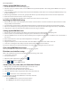
Nerve Integrity Monitor 9 10 11 9 Simulated patient with inserted electrodes (pads) 10 Simulated stimulus return plug for connection to the Patient Interface 11 Simulated electrode ground plug for connection to the Patient Interface 12 Simulated negative electrodes for connection to the Patient Interface 13 Simulated positive electrodes for connection to the Patient Interface 12 13 14 15 14 14 Stimulus plugs for connection to the Patient Interface.
Nerve Integrity Monitor C us e on ly , no t fo rM ed ic al us e You can select any procedure. For this assessment the assumption is that you have setup a custom procedure (refer to the System Setup/Custom Setup for instructions) called “Stimulation Test” and named the channels Ch 1, Ch 2, CH 3, CH 4. 3. Select User Profiles/ Stimulation Test. The Select Procedure SETUP screen appears. FC 4. Select a procedure. The Connect Devices screen appears. 5.
Nerve Integrity Monitor After Removal: • Channel 1 shows a lead off message. • After approximately a few seconds, the system displays “Lead Off” in yellow text on a zero (0) amplitude waveform line. 2. Reconnect the electrode and confirm the NIM Vital returned to normal operation. 3. Repeat test for all channels. Note: If any of these conditions are different, check your setup. If still incorrect, contact Customer service.
Nerve Integrity Monitor 3 al 2 1 us e 3. Touch and hold the stimulating probe to channel 1 of the Patient Simulator and observe the following: • Stimulus waveform on channel 1 (Refer to the Example Stimulus and Spike Waveforms). • Stimulus tone sounds (steady repeating beep). • Raw EMG can be heard (a popping sound accompanying the stimulus tone). • mA Measured is ± 5 % of the mA setting. • The system displays the μV reading to the right and above the zero (0) amplitude line in yellow and boxed. 4.
Nerve Integrity Monitor Troubleshooting Should you encounter any difficulty eliciting simulated responses from the NIM Vital system patient simulator, check the following: • Verify that the Stimulus Measured is approximately the same as the Stimulus Intensity. • Make sure the jumper cables are connected correctly between the SIMULATOR and PATIENT INTERFACE. • Adjust the EVENT THRESHOLD setting on the NIM Vital system. • Adjust the STIMULUS intensity on the NIM Vital system for adequate output.
Nerve Integrity Monitor Muting Detector setup Refer to Precaution P7. 1. Connect the mute probe adapter to the console. FC C us e on ly , no t fo rM ed ic al us e 2. Connect the mute probe to the mute probe adapter. 3. Open the Muting Detector jaws and insert the cable from the electrosurgical instruments ensuring that the wire is free to move and the jaws are completely closed. 4. Route the wire straight through the clamp.
Nerve Integrity Monitor Standard Clamping Monopolar and Bipolar (if needed) Clamping fo rM ed ic al us e Note: Bipolar clamping is normally not needed, but if power level is very low it may be necessary to loop the single conductor around and through the clamp. Refer to step 6 for clamping instructions. 5. Slide the cable so the probe is near the main unit of the electrosurgical instruments, not near the hand piece(s). 6.
Nerve Integrity Monitor Additional mute probe adapter information To remove the mute probe adapter from the console, squeeze the two tabs on the side of the adapter to release it. To tether the mute probe adapter to the muting detector, do the following: 1. Loop the mute probe adapter tether around the muting detector. 2. Take the end of the mute probe adapter marked with “Medtronic” and slip it through the tether, while going around the muting detector’s cable.
Nerve Integrity Monitor Bipolar Stimulating probes 8225351 8225451 Concentric Bipolar Stimulating Probe, 5/Box Prass Bipolar Stimulator Probe, 5/Box 8225401 1895825 1895824 Power Cord, 6 Meter, EU Power Cord, 6 Meter, U.K.
Nerve Integrity Monitor us e 1. Lock the castor wheels. 2. Slide the printer power isolator (Medtronic part # NIM4CC02 or NIM4CC03) into its cradle (opening on the right of the cradle) underneath the bottom shelf of the NIM Vital cart (figure figures 1 and 2), with the label side up and the two cords facing the rear of the cart. 3. Run the two cords to the rear of the cart, between the shelf and cart base (figure 3).
Nerve Integrity Monitor Prass Paired Electrodes. The electrodes are insulated to within 5 mm of the end with 5 mm spacing. Muscle-specific single use. Prass Paired Electrodes Small Hub. The electrodes are insulated to within 5 mm of the end with 2.5 mm spacing. Muscle-specific single use. Subdermal Needle Electrodes. Non-insulated high performance electrodes 12 mm long with a 0.4 mm diameter. al us e Electrode Ground (green with green wire) and Electrode Stimulus Return (red with white wire).
Nerve Integrity Monitor Fuses Console Replacement: the console AC power is fuse protected. Have a Biomedical Engineer check the fuse if a problem is suspected. It is very important that the correct replacement fuse is used (5 x 20 mm, 2.5 Amp, time-lag, Low breaking capacity, Xomed Fuse Kit # NIM4CFU1).
Nerve Integrity Monitor Patient Interface fuse replacement The Patient Interface has its own fuse. An LED underneath the fuse will blink white to indicate which fuse(s) need to be replaced. It is very important that the correct fuse is used – It must be Xomed Fuse Kit # 8253075 (similar 32 mA Type F 250V 5 x 20 mm fuses may not offer the same degree of protection).
Nerve Integrity Monitor Technical specifications Physical dimensions - console Size: Weight: 41 cm W x 45 cm D 42.5 cm H (Screen Open) 20.5 cm H (Screen Down for storage) 10.7 Kg Size: Weight: 6.5 cm W x 7.5 cm H x 21.5 cm D .55 Kg Size: Weight: Capacities: 53 cm W x 101 cm H x 61 cm DP 45 kg Drawer Max. Load - 4.5 kg Shelf Max. Load - 9.0 kg Cart Total Max. Load - 79.
Nerve Integrity Monitor Stimulus Range: Stim 1 and Stim 2 0-3 mA, a minimum of ±12 V compliance (tested into a 4K load) Stim 1 3.1-50mA a minimum of ±100V compliance (tested into a 2K load) Load Impedance Range: as long as the load impedance X stimulation current is less than or equal to the compliance voltage.
Nerve Integrity Monitor Cart Auxiliary AC output Power Isolator (See Printers listed in NIM Vital Compatible Accessories): Auxiliary AC output: (For Use With Approved NIM Accessories Only): Line Isolation: NIM4CC02 100-127VAC, 50-60 Hz, - 200VA NIM4CC03 220-240VAC, 50-60 Hz - 200VA - Continuous duty cycle – 200VA - 25% Intermittent duty cycle (Up to 5 minutes on at maximum 2X rated load then 15 minutes off ) NIM Printer Power Supply (# 8253025)150 VA Max.
Nerve Integrity Monitor The NIM Vital equipment cart The equipment cart serves as a convenient means to operate the NIM Vital in the operating room as well as store the console and accessories when not in use. NIM Vital lockdown no t fo rM ed ic al us e The Equipment Cart is supplied with a retaining screw with a four-arm knob which holds the NIM Vital console to the equipment cart. on ly , 1.
C FC e us ly , on no t al ed ic rM fo e us Nerve Integrity Monitor 74
Acoustic Neuroma 2 ch Brief 50 mS 500 uV Yes EMG + Event Tones 3.1 mS Acoustic Neuroma 4 ch 100 µV Largest Regular OFF STIM 2 Mode STIM 2 ON/OFF STIM 2 Pulse Width STIM 2 Current STIM 2 Warning Level STIM 2 Rate 1/sec ON 4/sec 3.0mA 0.0mA OFF STIM 2 ed ic rM 1.0 mA al Neck Dissection Neck Dissection 50 mS 500 µV 3.1 mS Parotid fo 0.8 mA no t Vagus STIM Nervassure 4/sec 1.
Nerve Integrity Monitor Legal information Contact information For further information regarding the use of this product or to report any problems, please contact Medtronic customer service at 1 800 874 5797; or refer to the last page of this manual for address information.
Nerve Integrity Monitor Guidance and manufacturer’s declaration - electromagnetic immunities - part II The NIM Vital is intended for use in the electromagnetic environment specified below. The customer or the user of the NIM Vital should assure that it is used in such an environment.
Nerve Integrity Monitor Limited warranty FC C us e on ly , no t fo rM ed ic al us e A. This Limited Warranty provides the following assurance for the customer who purchases a Medtronic NIM Vital System. This Limited Warranty is extended only to the buyer purchasing the NIM Vital System directly from Medtronic or from its affiliate or its authorized distributor or representative.
Nerve Integrity Monitor Glossary Console Radio Module. DSP Digital signal processor. EIC External Interface Controller. Event sequence A series of events separated from each other by less than one second. GUI Graphical user interface. Nervassure Automatic periodic stimulation. NIM Nerve Integrity Monitor, NIM Vital. NIM Vital See NIM PI Patient interface. PMB Power Management Board.
Nerve Integrity Monitor Buttons and indicators The “Buttons and indicators” topic contains all buttons the touch screen user interface displays and an explanation of how they work. Globally visible Multi-state for tabs: (Selected, available but not selected, disabled). Menu: Global settings. Confirm button. SETUP tab. Accept button. Cancel button. MONITORING tab. Dismiss button. Warning icon. Continue current case button. Click to enter patient data. Wireless connection details.
Nerve Integrity Monitor MONITORING Electrode check button. Snapshot button. Freeze button. Settings button. Decrease button. Increase button. Activate button. Slow APS Button. Fast APS button. Contextual help button. Operating side buttons (right currently selected, left currently unselected). Restart/start new baseline button. Next step button (baseline). Fix symbol Quick tag buttons (green is selected showing it has been taken).
Nerve Integrity Monitor REPORTS Save to .pdf button. Save Database button. Quick Tags report button. FC C us e on ly , no t fo rM ed ic al us e Print button.
C FC e us ly , on no t al ed ic rM fo e us Nerve Integrity Monitor 83
Symbols SN Serial number Do not dispose of this product in the unsorted municipal waste stream. Dispose of this product according to local regulations. See http://recycling.medtronic.com for instructions on proper disposal of this product. Do Not Use If Package Is Open Or Damaged. Package Contents Use By Date Precaution If the single use symbol is on the device label then this device is designed for single patient use only. Do not reuse, reprocess, or resterilize this product.
Symbols Conforms To IEC/EN60601-1 and ANSI/AAMI ES60601-1 Certified To CSA C22.2 No.60601-1 105345 Protective Earth Equipotential Consult Instructions for Use Caution Protects against water drops when the device is tilted up to and including 15°. e IPX2 Protected Against Vertical Water Drops. us IPX1 ed ic al Type BF Applied Part Manual Start/Stop rM Rf Transmitter (Interference May Occur). no t fo Follow instructions for use.
Europe/Middle East/Africa Medtronic Xomed Medtronic International Trading Sàrl Route du Molliau 31 Case Postale 84 CH- 1131 Tolochenaz Switzerland +41 21 802 7000 6743 Southpoint Drive North Jacksonville, Florida 32216-0980 USA medtronic.com +1 800 874 5797 Australia EC REP e Medtronic Australasia Pty Ltd 5 Alma Road Macquarie Park, NSW 2113 Australia Medtronic B.V.