
Users Manual Part 1

10
Nerve Integrity Monitor
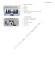
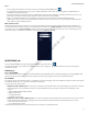
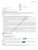
Patient Interface
1 Electrode ground. Signal return for patient electrodes.
2 Stimulating Instrument Jack or Stimulator Probes (Monopolar or
Bipolar).
3 Incrementing Probe Control Jack. Connects Incrementing Probe controls
to the NIM Vital.
4 Stimulus (out) Jack, negative (-).
5 Stimulus Return, positive (+).
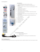
6 Patient Interface to console connector.
7 The Patient Interface fuses are for Stimulator Output and specically
tested for ECU protection.
8 Positive Electrode Jacks. Positive electrodes have matching color-coded
wires and plugs.
9 Negative Electrode Jacks. Negative electrodes have black wires and
color-coded plugs.
10 Patient Interface Clips.
11 Docking connector.
12 Battery indicator LED.
13 Fuse indicator LED.
14 Power button.
15 Spare fuses.
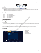
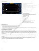
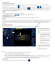
Incrementing Probe Adapter
1
2
1 Connect to Incrementing probe.
2 Connect to PI box.
Note: For use with prass incrementing probe (CFN 8225825 and CFN
8225490)
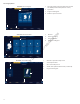
Incrementing probe
The (single use) incrementing probe provides the surgeon with the means to adjust the stimulation current at the surgical site. Refer
15
6
1
3
4
5
2
8 9
12
14
11
7
13
10
FCC use only, not for Medical use