Installation, Operation, and Maintenance Manual eHTX Series High Efficiency Separators 1365 North Clovis Avenue Fresno, California 93727‐2282 (559) 255‐1601 info@lakos.com www.lakos.
TABLE OF CONTENTS Page 2..…………………………Table of Contents Page 3..…………………………Principle of Operation Page 4..…………………………Pressure Drop vs. Flow Page 4..…………………………Separator Models Page 5..…………………………Installation Instructions Page 6..…………………………Inlet/Outlet Piping Page 7-8....……………………...Maintenance Page 9-11..…..………………….Trouble Shooting Page 12..…..…………………….Separator Manifolding Page 13...………………………..Spare Parts Page 14….....
Principle of Operation “How it Works” LAKOS eHTX Separators are designed specifically to remove solids from liquids. Each model is calculated for use within a prescribed flow range for maximum performance and solids removal. Flow rates above and below the recommended range may affect such performance.
Flow vs. Pressure Drop Chart eHTX Separator Model and Flow Chart Model Flow Range US gpm m³/hr eHTX‐0040‐V 40‐95 9‐21 eHTX‐0060‐V 60‐140 eHTX‐0080‐V Collection Chamber Capacity Inlet/Outlet Grooved Size Weight Empty Weight with Water gal liters lbs kg lbs kg 1‐1/2 inch 0.6 2.3 184 83 257 117 13‐31 2 inch 0.6 2.3 221 100 305 138 80‐185 18‐42 2‐1/2 inch 1.2 4.5 298 135 456 207 eHTX‐0090‐V 90‐230 20‐52 3 inch 1.2 4.
Installation Instructions 1. LAKOS Separators are shipped on steel skids or in wooden crates. Support legs (22 ½° low profiles only) are detached. Lifting lugs, located on the unit’s side and/or flanges, are provided for hoisting as necessary. 2. A suitable foundation is necessary to accommodate the LAKOS Separator’s weight including liquid. Anchor bolts are recommended in the base of the legs (low profile) or skirt (vertical profile). 3.
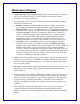
Recommended Inlet & Outlet Piping The inlet and outlet piping of a separator are important for controlling vibration of the unit. The vibration is more prevalent in units larger than 6”, however, LAKOS recommends the illustration configuration below be followed on all units. The factory should be consulted on units larger than 6” if configurations cannot be followed.
Maintenance/Purging 1. LAKOS Separators must be purged regularly. The over-accumulation of separated solids will overfill the separator’s collection chamber, substantially affecting performance and causing undue wear. 2. Several purging options are available and all may be performed while the LAKOS Separator is in full operation. a. Manual: A full-port, straight-through valve may be installed on the standard purge opening and actuated manually as necessary to purge separated solids. b.
Maintenance Recommendations LAKOS recommends periodic inspections of the separator to keep performance at an optimum level. 1. Flange gaskets or victaulic gaskets should be checked for leaks and replaced as necessary. Gaskets should be replaced at disassembly of separator. 2. Hand hole clean-out: Hand hole should be removed to inspect the collection chamber for unwanted build up.
Trouble-Shooting Guidelines for Separator Installations 1. Verify Actual Flow Rate: Use pressure gauges to indicate differential pressure and flow meter to verify flow rate. (Multiple pumps used to increase flow are installed in parallel (into common manifold); multiple pumps to increase pressure are installed in series (one after another). Flow meters should be installed prior to the separator. Flow meters installed after the separator will indicate erroneous data. 2.
5. Vertical Units: Be aware that solids may accumulate within the separator for a period of time until the solids reach the level of the purge outlet. The purge outlet is not flush with the bottom of the solids collection chamber. 6. Purging: Purge line piping should be as straight as possible to desired disposal destination. Avoid uphill piping, multiple elbows and low points where solids may accumulate and block the piping.
8. Additional Installation Piping for Separator Accessiblity: Separators which feature a removable upper chamber should be installed with a spool in order to facilitate the removal of the upper chamber. 9. Flanges/Couplings: All flanges and/or grooved couplings should have the appropriate gasket/seal in order to ensure a leak-free installation. All hand hole clean-out ports and other internal access devices should also be properly re-sealed after use. 10.
Separator Manifold 12
eHTX Spare Parts List eHTX-0040-V PART# DESC DESCRIPTION TWO DESCRIPTION THREE 120761 SHEET RUBBER ¼” THK 2-3/4"OD x 1-15/16” ID DESCRIPTION FOUR EPDM 106147 GASKET COUPLING 8 TYPE E GROOVE EPDM 118512 GKT KIT GAUGES 0- 160PSI ASSEMBLY eHTX-0060-V PART# DESC DESCRIPTION TWO DESCRIPTION THREE 120761 SHEET RUBBER ¼” THK 3" OD x 2-7/16” ID DESCRIPTION FOUR EPDM 106147 GASKET COUPLING 8 TYPE E GROOVE EPDM 118512 GKT KIT GAUGES 0- 160PSI ASSEMBLY DESCRIPTION FOUR eHTX-0080-
Notes: Separator Model:___________________________________________________ Sales Order #:______________________________________________________ Purchase Date:_____________________________________________________ Distributor:________________________________________________________ System Flow:_____________________ Separator Delta P:_________________ 1365 North Clovis Avenue Fresno, Ca 93727-2282 Fax: 1-559-255-8093 Phone: (559)255-1601 info@lakos.com www.lakos.