MXB-360 360,000 BTU BOILER Installation and Operating Instructions ® Lanair Waste Oil Heaters & Boilers 4109 Capital Circle Janesville, Wisconsin 53546 608-752-1601 www.lanair.
® BEFORE YOU BEGIN INSTALLATION... Read and understand this manual completely before beginning installation. Code Requirements Installation must comply with all state, local and utility codes, laws, regulations and ordinances and CSA standard B139. When required, installations must conform to A.S.M.E. safety code for controls and safety devices for automatically fired boilers No. CSD-1.
MXB 360 360,000 BTU BOILER Installation and Operating Instructions Table of Contents: Code Requirements and Rules For Safe Installation and Operation . . . . . . . . . . . . . . . . page 2 Sec. 1 General Specifications . . . . . . . . . . . . . . . . . . . . . . . . . . . . . . . . . . . . . . . . . . . . . . . . . . . . . . . . . . . . . . . . . . . page 4 Sec. 2 Typical Boiler Room Layout . . . . . . . . . . . . . . . . . . . . . . . . . . . . . . . . . . . . . . . . . . . . . . . . . . . . . . . . . .
Section 1 - Burner Specifications 2 1 3 6 7 4 5 8 9 10 11 No. 1 2 3 4 5 6 7 8 9 10 11 4 Description Mounting Plate Ignitor Transformer Fuel Line Inlet Fuel Pressure Gauge Combustion Air Baffle View Port Oil Primary Safety Control Waste Oil/Fuel Oil Switch Quick Disconnect Receptacle Air Supply Inlet Combustion Blower Motor Burner Assembly-Performance Ratings Voltage . . . . . . . . . . . . . . . . . . . . . . . . . . . . . . . . 115 vac Cycles . . . . . . . . . . . . . . . . . . . . . . . . . .
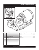
Section 1 - Pump Specifications 2 3 OPTIONAL J-PUMP 8 5 9 4 7 6 1 No. 1 2 3 4 5 6 7 8 9 Description Pump Platform Pump Motor Adapter Shaft Cover Pump Pressure Gauge port Easy Flow Bleed Valve 1/4" NPT Inlet 1/8" NPT Outlet Adapter Shaft Pump Assembly-Performance Ratings Voltage . . . . . . . . . . . . . . . . . . . . . . . . . . . . . . . . 115 vac Cycles . . . . . . . . . . . . . . . . . . . . . . . . . . . . . . . . . . . . 60 hz Weight . . . . . . . . . . . . . . . . . . . . . . . . . . . . . .
Section 1 - Boiler Specifications 8 12 DETAIL A 11 9 Supply 10 5 Relief Valve MX BOILER Supply Manifold (see Detail A) 2 4 1 3 6 Electrical Junction Box Flow Switch (not included) Return 7 No.
Section 1 - Boiler Specifications TOP 10 11 REAR 12 Clean-Out Port Clean-Out Port 14 13 SIDE FRONT 9 8 2-1/2” MPT Supply 1 7 2-1/2” FPT Return 4 2 5 6 3 No. 1 2 3 4 5 6 Dimension 36" 33" 73-3/8" 12" 52" 8" No. 7 8 9 10 11 12 Dimension 3/4" 9-3/8" 7-3/4" oc 18" oc 5" oc 29-1/2" oc No. 13 14 Dimension 4" oc 20" oc Visit our website at: www.lanair.
Section 2 - Typical Boiler Room Layout 8” 8” Boiler Vent Connections CL 2-1/2” Boiler Supply Connection 2“ 8“ CL CL 33” 16.5” min. 47.5” 16.5” 16.5” CL Dimension as per job specifications and local codes Figure 1 Section 3 - Boiler Room Air Requirements ! WARNING: Failure to provide an adequate supply of fresh air for combustion will result in hazardous operating conditions. Do not use an exhaust fan in the boiler room. 1.
Section 3 - Boiler Room Air Requirements Figure 2 12" Maximum Louvered openings for ventilation & combustion 12" Maximum When air comes directly from outdoors, again use two openings as explained on page 8 and above except: • Direct connection or vertical ducting allow 1 sq. inch per 4,000 BTU/HR. • Direct connection through horizontal ducting allow 1 sq. inch per 2,000 BTU/HR • All ducting shall be the same size as opening but no less than 3" x 3" or 9 square inches.
Section 4 - Chimney or Vent System ! Failure to provide proper venting of the boiler exhaust gases could result in death, serious injury, and/or property damage. FOLLOW CHIMNEY MANUFACTURERS INSTRUCTIONS. Class "A" Chimney Cap 3' taller than any objects within 10' 8" Class "A" Chimney NOTE: Class "A" components require a 2" clearance from combustible materials.
Section 4 - Chimney or Vent System 8. Do not use more than one 90° elbow. Each 90° elbow equals a 10’ run of chimney. The maximum run for the chimney connector is 30’. 9. Secure all connections in the chimney connector with 3 screws per joint. 10. The chimney connector clearance to any combustible material is 18”. The Class "A” chimney clearance to any combustible is 2”. FOLLOW THE CHIMNEY MANUFACTURER’S INSTRUCTIONS. 11.
Section 6 - Fuel Supply Tank Installation Figure 4 3/8” Fuel Line To Burner (not included) 3/8” Copper Tube P/N 9182 Fuel Regulator Assembly (see page 14) Vent 1“ x 1/2” bushing P/N 8904 PUMP ASSEMBLY 1/4” Nipple P/N 8647 1/4” x 1/2” Coupling P/N 8558 1“ x 1/2” bushing P/N 8904 Fill STORAGE TANK TOP VIEW Vacuum Gauge P/N 8398 1/2” x 1/4” x 1/4” Tee P/N 9412 3/8” Fuel Line To Burner (not included) PUMP ASSEMBLY Primary Strainer P/N 9807 STORAGE TANK 1/2” pick-up tube (not included) Check Valve
Section 7 - Fuel Supply Pump/ Piping General Requirements - Fuel Tank 1. The fuel supply tank and supply lines must be installed in accordance with the National Fire Protection Association requirements, as well as state and local ordinances. 2. Regulations require oil storage tanks located inside a building not exceed 275 gallons individually and are not to exceed 550 gallons in one building. Check state and local codes. 3.
Section 7 - Fuel Supply Pump/ Piping NOTE: This item comes pre-assembled from the factory. FUEL LINE TO BURNER 3/8” x 1/4’” NPT P/N 8939 Tee P/N 8909 Fuel Regulator P/N 8460 Fuel Relief Valve P/N 8470 Close Nipple P/N 8647 Bushing P/N 8908 RETURN LINE TO TANK 3/8” x 1/4’” NPT P/N 8939 Nipple P/N 8915 Figure 5 10. Install the check valve (arrow facing towards the pump) on the bottom of the pick up tube. 11. Install a vacuum gauge (included, P/N 8398) in the suction line.
Section 8 - Typical Boiler Piping Figure 6 Single Boiler Piping with Blend Pump ! ATTENTION: Heating system design and burner operation must incorporate interlock to prevent burner from firing when boiler has no system water flow. Air Separator Amtrol #720 Air Eliminator or Equal System Supply System Circulator Blend Pump * Check Valve Pressure Reduction Valve Backflow Preventer Expansion Tank From City Water Supply *16.
Section 9 - Boiler Installation ! All MX Series boilers are shipped with the boiler sections assembled and hydrostatically tested to A.S.M.E. at the factory. Inspect boiler for any visible damage before beginning installation. Inspect Shipment Any claims for damage or shortage must be filed against carrier or consignee. No claims for variances from, or shortages in orders, will be considered unless presented 7 days after receipt of goods. Boiler shipment comes in two separate pallets. 1.
Section 9 - Boiler Installation ! Note: Threads used on the studs is metric. Any attempt to use standard (English) threaded studs in place of those supplied will damage the boiler block. Figure 7 (4) 12mm x 50mm studs Gasket (4) 12mm washers TOP OF BOILER (4) 12mm nut Supply Manifold Manifold and Diffuser Installation 1. Attach supply manifold as indicated in Fig. 7. Install return port diffuser and attach return flange as shown in Fig. 8. NOTE: Make sure diffuser slots face upward (see Fig. 8).
Section 9 - Boiler Installation Figure 9 086 038 036 094 033 060 030 040 018 043 018 093 041 ! ATTENTION: DO NOT INSTALL THE BOILER JACKET WITHOUT FIRST ATTACHING THE SUPPLY MANIFOLD AND DIFFUSER (SEE PAGE 17).
Section 9 - Boiler Installation Boiler Jacket Installation 1. Screw the four (4) jacket extensions (043) into the the four outer holes in the corners of the rear boiler section. Securely tighten the jacket extensions. Check other bolts on the rear panel and tighten if necessary. 2. Place the large wrap-around insulation blanket (040) over the boiler block. NOTE: The aluminum foil side of the blanket should be facing out. 3. Place smaller piece of insulation (030) on top of the insulation blanket.
Section 10 - Boiler Controls and Accessory Location Figure 11 pressure relief valve MX BOILER Aquastat Electrical Junction Box Burner Service Switch ! INSTALLATION MUST BE DONE BY A LICENSED HVAC/HYDRONIC CONTRACTOR FAMILIAR WITH ALL STATE AND LOCAL CODES. Boiler Controls and Accessory Location 1. 2. Remove the top of the boiler jacket. Install 3/4" x 6" relief valve pipe to the top of the unit as indicated in Fig. 12. Pipe mounts to the 3/4" hole at the top rear of the boiler block.
Section 10 - Boiler Controls and Accessory Location ! Discharge piping from pressure relief valve must be piped to a drain or must terminate 6" above floor to avoid damage to the structure or personal injury. It must NOT be piped to a point where freezing might occur. low water cut-out Figure 13 6. Install discharge piping from pressure relief valve. 7. Install 3/4" pipe extension to supply manifold. Attach sensor housing to the extension.
Section 12 - Electrical Connections ! CAUTION: HAZARD OF ELECTRICAL SHOCK! Main Electrical Installation 1. All wiring must comply with the National Electrical Code. State and Local Ordinances, and be wired by a qualified electrician. 2. Electrical service MUST be connected to a separate 20 AMP, 115 VAC, 60 HZ single phase circuit. 3. Electrical service connections are made in the electrical junction box on side of the boiler. 4.
YELLOW YELLOW PUMP MOTOR TO THERMOSTAT OR JUMPER (DEPENDING ON INSTALLATION) ORANGE COMBUSTION BLOWER OIL PRIMARY WHITE WHITE ORANGE RED WHITE WHITE WHITE WHITE TRANSFORMER MAIN POWER IN 120 VOLT WHITE BLACK BLUE (NOT USED) AIR SOLENOID BLUE PURPLE RED WHITE WHITE ORANGE BLACK ORANGE WHITE WHITE F2 F1 T2 T1 PRE-HEATER SWITCH SNAP DISK AIR PRE-HEATER TO HI-LIMIT SWITCH AND SUPPLY MANIFOLD CONTROLS OIL PRE-HEATER BLACK RED Figure 15 MANUAL RESET Section 12 - Burner/Pump El
Section 13 - Compressed Air Installation Compressed Air Supply Installation 1. Install an air pressure supply line connection to the air filter/regulator. 2. The air supply source must be capable of producing 1.0 CFM @ 100 PSI. 3. Install a shut off valve in the air supply line for service. 4. Install a primary air filter/regulator with a gauge (capable of reading line pressure) in the air supply line prior to the air filter/regulator mounted on the furnace.
Section 14 - Controls Burner Controls and Operation • Oil Primary Safety Control/Cad Cell: The oil primary control is mounted on top of the burner’s electrical box. When the thermostat calls for heat the oil primary control starts the burner by switching on the air solenoid valve, ignition transformer, combustion air blower, and the fuel pump. The oil primary control works in conjunction with the cadmium sulfide cell (cad cell). The cad cell is mounted inside the burner cover, and faces the flame.
Section 14 - Controls Fuel Pump Controls and Operation • Fuel Regulator: A Fuel regulator is used to adjust the fuel pressure of waste oil to the burner. • Fuel Relief Valve: The fuel relief valve prevents excess pressure build-up in the fuel line upon burner shut-down. Boiler Controls and Operation • Hi-Limit Switch: Hi-limit switches are immersion type devices for regulating the temperature of liquids in a boiler where temperature control is required.
Section 15 - Start-Up Procedures Waste Oil Burner Start-Up 1. Make sure the main electrical service for the heater is turned off, and locked out. 2. Fill the oil supply tank with an approved fuel to a level that is above the pick-up tube check valve. 3. Check for proper draft in the chimney. The draft must read -.02 W.C. cold. 4. Make sure there is air pressure at the heaters air filter/regulator, set it at 12 PSI. Set the primary regulator on the air supply line to 30 PSI. 5.
Section 16 - Priming the Fuel Pump 1. The fuel level in the supply tank must be above the check valve on the pick-up tube. Fill suction line with oil. Figure 17 2. Remove the bowl of the suction line strainer, and fill with clean fuel. Replace the strainer bowl. 3. Remove the two yellow wires from the F-F terminal on the oil primary control (Fig. 17). Install a jumper wire between the F-F terminals (Fig. 18). 4. Adjust the air filter/regulator on the heater to –0- PSI. 5.
Section 17 - Flame Adjustment Flame Adjustment 1. Start boiler, let it run for at least 45 minutes to reach operating temperature before proceeding. 2. Check chimney draft, set the barometric damper to -.06 WC when hot and running. 3. Check the atomizing air pressure, set the air filter/regulator on the heater to 15 PSI as a starting point. 4. Check the fuel pressure gauge on the burner, set to: 7 LBS. Adjust the screw on the fuel regulator. Lock into position.
Section 17 - Flame Adjustment Flame Adjustment - Visual Flame is over-fired (Fig. 20). • Dark yellow, to orange in color. • The flame is hitting the walls, filling the chamber with a smokey flame. Correct immediately or chamber may be damaged. • Decrease fuel pressure, and adjust combustion air baffle. Air pressure may also need to be adjusted. Problem: Too large of a flame, dark yellow in color. 1. Too much fuel pressure. 2. Not enough combustion air. 3. Not enough atomizing air pressure. 4.
Section 18 - Service / Maintenance MX SERIES BOILER SERVICE / MAINTENANCE SCHEDULE DAILY WEEKLY MONTHLY ANNUALLY (Season Shut Down) • Check fuel supply tank level. • Check vacuum gauge reading on suction line. See Section 19. • • • • • Drain water/ anti-freeze from the fuel supply tank. • Check the combustion chamber flue passages. Clean if needed (see page 32). • Shut off main power supply to boiler. • Perform monthly serv• Check the air pressure ice/maintenance.
Section 18 - Service / Maintenance ! ! NOTE: ALWAYS WEAR EYE, FACE AND BREATHING PROTECTION AND PROTECTIVE CLOTHING WHEN INSPECTING OR CLEANING CHAMBER. WARNING: DISCONNECT ALL ELECTRICAL POWER TO BOILER BEFORE SERVICING! Flue/Combustion Chamber Cleaning 1. The boiler core must be completely cool to the touch before attempting to clean. 2. Turn off all power to the boiler (120 VAC) at the main disconnect. 3. Turn off air pressure supply 4.
Section 18 - Service / Maintenance Cleaning Suction Line Strainer bolt The suction line strainer should be cleaned every 30 days of operation. The element is a washable metal element. If your waste oil is extremely dirty, this strainer may need to be cleaned more frequently. Your vacuum gauge will help you determine when the filter needs cleaning. The vacuum gauge reading should not exceed 5" HG of vacuum. If it does, the strainer needs cleaning. washer o-ring outlet 1” NPT 1.
6 7 3 4 8 2 Part No. 9853 7004 9758 9870 9814 3730 9870 7418 3726 9870 9870 9856 9870 9870 9835 9838 9870 9871 9871 9871 Qty.
Section 18 - Service / Maintenance 1. Remove Pre-Heater Assembly • Disconnect the air line from the brass fitting on the air pre-heater and then from the air solenoid and remove. • Disconnect wiring from the oil pre-heater cartridge, air pre-heater cartridge and snap disc assembly in the wiring junction box. • Disconnect fuel line and fitting (6) from the oil block (5). • Disconnect fuel pressure gauge (8) and fitting from the oil block (5). • Remove button hex screw (14) and washer (11).
Section 18 - Service / Maintenance Annual Maintenance - Oil Pre-Heater Oil Pre-Heater Tune -Up Kit (PN# 9869) Required. 13 12 12 10 12 5 9 4 7 11 6 14 7 6 1 2 8 3 Ref. No. 1 2 3 4 5 6 7 8 9 10 11 12 13 14 Part No. 8992 9813 9869 9869 2901 9029 9869 8498 7242 9869 7418 7109 9366 7242 Qty.
Section 18 - Service / Maintenance 1. Separate Air Pre-Heater from Oil Pre-Heater • Remove o-ring and discard(10). 2. Disassemble Oil Pre-Heater • Remove o-ring and discard(10). • Remove six hex cap screws (3) from face plate (2) and discard. • Remove oil cartridge heater (1). • Remove four 13/16"OD o-rings and discard(4). • Remove three plugs (12) from oil block (5) • Remove hex cap screw (9) from inside oil pre-heater block and clean. NOTE: Do not discard (5). 3.
Section 18 - Service / Maintenance Ignitor Replacement / Adjustment electrodes should extend approximately 1/8” beyond nozzle tip 1. Disconnect power to the boiler. 2. Remove the pre-heater assembly from the burner housing. Disassemble and clean all parts as instructed on pages 34-37. 3/8” 3. Using a 7/16" wrench, carefully remove the one-piece ignitor from the air preheater. 1/16” Side View 4. Install a new one piece ignitor (P/N 3730) to the top of the air preheater.
Section 18 - Service / Maintenance Air Pre-Heater Diaphragm Replacement o-ring diaphragm 1. Remove the four hex cap screws from the diaphragm assembly and discard. piston 2. Disassemble and discard diaphragm, spring and o-ring . hex cap screws 3. Thoroughly clean remaining parts. spring 4. Re-assemble using new diaphragm, o-ring, spring and hex cap screws. Air Pre-Heater Nozzle Cleaning / Replacement 1. Periodic cleaning of the nozzle assembly may be required. 2.
Section 19 - Troubleshooting Symptom Possible Cause Corrective Action A. Burner will not start 1. Main electrical power circuit breaker tripped 1. Reset breaker 2. Service disconnect switch off or fuse blown 2. Turn switch on or replace fuse 3. Thermostat turned down/ improperly installed/ defective 3. Turn thermostat up, check wires/test components/replace 4. Oil primary safety tripped/defective 4. Reset/test components, replace if needed 5. Too much light showing on cad cell/defective 5.
Section 19 - Trouble-Shooting Symptom Possible Cause Corrective Action C. Burner fires, and then fails on oil primary safety 1. Contaminated fuel supply (water/anti freeze/gear lube) or dirty fuel filter. 1. Drain and clean fuel supply tank. Clean fuel filter (see page 33) 2. Improper draft 2. Check draft see page 10. Make sure chimney is properly installed 3. Plugged heat exchanger, manifold, or chimney 3. Clean heater including manifold, and chimney 4. Wrong air pressure 4.
Section 20 - Warranty LANAIR 1O YEAR WASTE OIL BOILER LIMITED WARRANTY Lenan Corp., MANUFACTURER, hereby warrants that manufacturer’s products shall be free from defect in material and workmanship under normal use according to the provisions and limitations herein set forth.
Section 21 - Burner Reference Diagram Ignitor Manual Reset & Snap Disk Fuel Supply Oil Pre-Heater Block Air Solenoid To Combustion Blower Air Supply Pre-Heater Adjustment Screw Air Supply Air Pre-Heater Block Electrical Quick Disconnect Oil Pressure Gauge Pre-Heater Switch View Port To Transformer To “F” Terminals To Oil Primary Cad Cell Cover Burner Cover Visit our website at: www.lanair.
® Lanair Waste Oil Heaters & Boilers 4109 Capital Circle Janesville, Wisconsin 53546 608-752-1601 www.lanair.