
User guide

Visit our website at: www.lanair.com
19
Section 9 - Boiler Installation
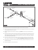
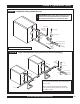
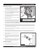
Boiler Jacket Installation
1. Screw the four (4) jacket extensions (043) into the the
four outer holes in the corners of the rear boiler section.
Securely tighten the jacket extensions. Check other
bolts on the rear panel and tighten if necessary.
2. Place the large wrap-around insulation blanket (040)
over the boiler block. NOTE:The aluminum foil side of
the blanket should be facing out.
3. Place smaller piece of insulation (030) on top of the
insulation blanket. This will provide extra insulation on
the top of the boiler block.
4. Remove flue collector clean-out covers (see illustration
on page 7 for location).
5. Place rear insulation (060) on the rear panel. The holes
of the insulation should align with the clean-out ports
and the jacket extensions (043). Compress insulation
until the jacket extensions (043) protrude. NOTE:The rear insulation is two separate pieces (right and left) Position
with the aluminum foil side of the insulation facing out.
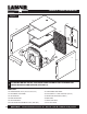
6. Align the right rear jacket panel (036) to the jacket extensions (043) and attach using two (2) M6 x 10 pan head
screws provided. Align the left rear jacket panel (038) to the jacket extensions (043) and attach using two (2) M6 x
10 pan head screws provided. Align the corresponding holes of the right and left rear jacket panels and secure
using five (5) sheet metal screws provided.
7. Re-attach the flue collector clean-out covers. NOTE: Do not over tighten bolts of the clean-out covers. Over tight-
ening may crack or break the covers.
8. Attach the right (093) and left (094) jacket panels. Each panel attaches to the unit using the hooks on the factory-
installed hinge brackets (018) at the front of the unit and the holes in the previously mounted rear panels.
9. Place the center panel (033), with flange edge down,
between side panels.
10. Attach the upper front trim panel (041) between the
right (093) and left (094) side panels. The front panel has
hooks which are inserted into slots in the front of the
side panels.
11. Align the hooks of the top panel (086) with those of slots
on the top of the side panels. Place top panel between
side panels and slide forward to lock in position.
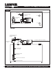
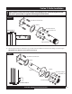
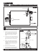
Cap
Gasket
Lens
Sight Glass Installation
1. Remove the sight glass plug on the door of the unit.
2. Install sight glass assembly. Hand tighten (Fig. 10).
Figure 10
ATTENTION: THIS BOILER REQUIRES A LINER
(INCLUDED) FOR OPERATION. DO NOT
OPERATE BOILER WITHOUT LINER IN PLACE.
!