
Product Manual
PAGE 3
WARNING - IMPORTANT ELECTRICAL GROUNDING INFORMATION:
1. To reduce the risk of electrical shock from metal parts of the installation other than the pump, bond together all metal
parts accessible at the well head (including metal discharge pipe, metal well casing, etc.). Use a metal bonding
conductor at least as large as the power cable conductors running down the well to the pump’s motor.
2. Clamp or weld (or both) this bonding conductor to the grounding means provided with the pump, which will be the
equipment-grounding terminal, the grounding conductor on the pump housing or an equipment-grounding lead. The
equipment-grounding lead, when provided, will be the conductor having green insulation.
3. Ground the pump, motor and any metallic conduit that carries power cable conductors. Ground these back to the
service by connecting a copper conductor from the pump, motor and conduit to the grounding screw provided
within the supply-connection box wiring compartment. This conductor must be at least as large as the circuit
conductors supplying the pump.
BEFORE LOWERING PUMP INTO WELL:
1. Smoothoutanyroughspotsoredgesonthetoplipofthewellcasingwithahammerormetalletopreventdamagetothe
pump or power cables, when lowering into well.
2. Make sure a check valve is installed (built-in or externally mounted just above pump).
3. Installatorquearrestorjustabovethepumptopreventchangofcablewhenpumpandpipetwistduringstartingand
stopping.
4. Attachabrassorstainlesssteelmaleadaptortothetopendofpump/checkvalveandtightlyclamp/bandPVCorexible
polyethylene pipe to the adaptor.
5. Topreventlosingpumpdownthewell,connectasafetyropestrongenoughtosupportpumpanddroppipe(minimum¼”
twisted polypropylene rope) to eyelet on pump discharge or male adaptor. Tie off other end of safety rope, securely to well
seal,well cap or pitless adaptor.
6. Clamp or tape (industrial grade PVC electrical tape) power leads to plastic pipe within 6” of the pump
discharge,leaving4”-5”ofslackinleadsatthispoint,toallowforstretchingofpipewheninstalledinwell.
7. Clamp or tape (industrial grade PVC electrical tape) power cables and safety rope to the pipe every 10’, straight up from
the bottom to top. DO NOT spiral cable around the pipe. DO NOT allow any excess cable between bands; cable must be as
atagainstpipeaspossible.
LOWERING PUMP INTO WELL:
1. Take care when beginning to lower pump down the well casing. DO NOT let the pump, cables or pipe rub against the well
casing. DO NOT let the cable insulation drag or scrape over the top lip of the casing.
2. Lower the pump into the well slowly without forcing. Use a foot clamp to hold galvanized or PVC pipe while connecting the
next length of pipe and taping the power cables and rope. As you add sections of galvanized or PVC pipe, apply sealant only
to the male threaded ends of each section and tighten to next section. NEVER allow pump cable to support weight of pump.
3. Install additional spring-loaded check valves at 100’ intervals to prevent water shock from traveling back to pump.
4. Lowerpumpatleast10’belowthemaximumdrawdownofthewaterlevel,ifpossible,andnevercloserthan5’fromthe
bottom of the well.
5. Whenawellsealisused,installacoupling,elboworteeonthetopendofthelastverticallengthofpipeandallowthettingto
restontheoutsideofthewellsealtosupportthepipe,powercables,safetyropeandpump.Mostwellsealshaveattingto
sealthepowercables,butifnosuchttingisprovided,conduitmustbeusedtoprotect
cables and prevent water and foreign matter from leaking into well around cable.
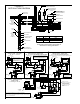
6. In installations where the pipe from the well seal to the water tank is subject to frost or freezing conditions, a pitless installation
is recommended (see Fig.1).
7. Use an ohmmeter to make insulation and continuity checks on the cable after the pump is installed. This locates any fault in
the cable.
CONNECTING PRESSURE SWITCH & POWER CABLES:
Employ a licensed electrician to do the wiring.
All wiring must be done in accordance with applicable national and local electrical codes.
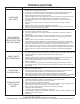
RefertoeitherFig.2,3,4or5fortypicalinstallationwiringdiagrams.
Power supply is wired directly from the main switch to a separate fused disconnect switch. Consult electrician or dealer for correct
circuit breaker or fuse amp rating.
• All single phase motors are automatically protected against overload damage by built-in thermal control element.
• Three phase motors require a magnetic starter equipped with three-leg protection having quick-trip, ambient
compensated overloads (heater) of correct size for the horsepower of the motor. Consult dealer or electrician.
Use an ohmmeter to make continuity and insulation checks after the installation is complete.
NOTE: For three (3) wire single phase pumps, connect the three (3) colored wires of the pump cable to the
matching black, red and yellow terminals of the motor control box, i.e. always connect like colors.
For two (2) wire single phase pumps, connect pump cables directly to load terminals of the pressure
switch (color matching is not necessary).
NOTE: Refer to Pre-installation Preparation section of this manual for information regarding lightning arrestors.