
Paper Shredder User Manual


4
Manual No. 330-148M 8/20/07
Land Pride
Shredder Assembly Instructions
■
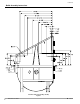
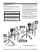
Center Deck & Left Wing Shredder Assy
Refer to Figure 4:
1. Attach center deck and left wing shredder
assemblies (#2) to gearbox output shafts (B) with
existing washer (C) and slotted hex nut (D). Torqued
slotted nut to 550 ft./lbs.
2. Install cotter pin (E) in the slotted nut with legs
securely bent around the nut.
Center Deck & Left Wing Shredder Assemblies
Figure 4
Counterclockwise Rotation
25601
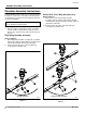
Shredder Assembly Instructions
A detailed listing of parts for this accessory kit is provided
on page 6. Use the list as a checklist to inventory parts
received. Please contact your local Land Pride dealer for
any missing hardware.
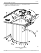
Refer to Figure 3:
1. Remove all three existing blade carrier assemblies
from the gearbox output shafts (A & B). Keep flat
washers C), slotted hex nuts (D) and cotter pins (E)
for reuse.
Right Wing Shredder Assembly
Refer to Figure 3:
1. Attach right wing shredder assembly (#1) to gearbox
output shaft (A) with existing washer (C) and slotted
hex nut (D). Torqued slotted nut to 550 ft./lbs.
2. Install cotter pin (E) in the slotted nut with legs
securely bent around the nut.
Right Wing Shredder Assembly
Figure 3
IMPORTANT: Read “Safety Information” on page 1
before installing shredder blades.
Clockwise Rotation
25601