LT230T TRANSFER GEARBOX Overhaul Manual LT230T Verdeelbak revisieboek LT230T Boîte de transfert Manuel de révision LT230T Verteilergetriebe Überholungsanleitung LT230T Riduttore Manuale di revisione LT230T Caja de transferencia Manual de revisión LT230T Caixa de velocidades manual Manual de revisão
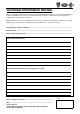
Technical Information Review While every attempt is made to ensure that the technical information we supply is as accurate and up to date as possible, from time to time, errors do occur. There may also be instances where the style or content of our publications do not meet your exact needs. We would value your assistance in helping us to improve the quality of our publications and invite you to submit details of any technical errors, or improvements you would like to see, in the space below.
LT230T TRANSFER BOX OVERHAUL MANUAL This transfer box is fitted to the following models: Serial No. Prefixes 20D, 22D and 32D - Defender Serial No. Prefixes 28D and 34D - Discovery Serial No. Prefixes 14D, 15D, 20D, 26D, 27D, 28D and 30D - Range Rover Classic Publication Part No.
INTRODUCTION CONTENTS Page INFORMATION INTRODUCTION ...................................................................................................... 1 REPAIRS AND REPLACEMENTS ........................................................................... 2 SPECIFICATION ......................................................................................................
INTRODUCTION INTRODUCTION How to use this manual References To assist in the use of this manual the section title is given at the top and the relevant sub-section is given at the bottom each page. Operations covered in this manual do not include reference to testing the vehicle after repair.
INTRODUCTION REPAIRS AND REPLACEMENTS SPECIFICATION When replacement parts are required it is essential that only Land Rover recommended parts are used. Land Rover are constantly seeking to improve the specification, design and production of their vehicles and alterations take place accordingly. While every effort has been made to ensure the accuracy of this Manual, it should not be regarded as an infallible guide to current specifications of any particular component or vehicle.
TRANSFER BOX CONTENTS Page DESCRIPTION AND OPERATION FRONT OUTPUT HOUSING COMPONENTS ......................................................... 3 DIFFERENTIAL COMPONENTS .............................................................................. 5 MAIN CASING COMPONENTS ............................................................................... 7 REAR OUTPUT HOUSING AND TRANSMISSION BRAKE COMPONENTS .......... 9 DESCRIPTION ...........................................................................
TRANSFER BOX CONTENTS Page Neutral warning lamp switch - if fitted - not Range Rover Classic ........................... 51 Differential lock warning lamp switch - adjust ......................................................... 51 Transmission brake .................................................................................................
TRANSFER BOX CONTENTS Page DATA, TORQUE & TOOLS DATA ........................................................................................................................ 1 TORQUE FIGURES .................................................................................................. 2 SERVICE TOOLS .....................................................................................................
TRANSFER BOX This page is intentionally left blank DESCRIPTION AND OPERATION 1
TRANSFER BOX 2 DESCRIPTION AND OPERATION
TRANSFER BOX FRONT OUTPUT HOUSING COMPONENTS 1. 2. 3. 4. 5. 6. 7. 8. 9. 10. 11. 12. 13. 14. 15. 16. 17. 18. 19. 20. 21.
TRANSFER BOX 4 DESCRIPTION AND OPERATION
TRANSFER BOX DIFFERENTIAL COMPONENTS 1. 2. 3. 4. 5. 6. 7. 8. 9. 10. 11. 12. Retaining ring Differential carrier - rear half Low range gear High/low hub High/low selector sleeve High/low selector shaft High/low selector fork Setscrew - high/low selector fork High range gear High range gear bush Differential rear bearing Bearing outer track 13. 14. 15. 16. 17. 18. 19. 20. 21. 22. 23.
TRANSFER BOX 6 DESCRIPTION AND OPERATION
TRANSFER BOX MAIN CASING COMPONENTS 1. 2. 3. 4. 5. 6. 7. 8. 9. 10. 11. 12. 13. 14. 15. 16. 17.
TRANSFER BOX 8 DESCRIPTION AND OPERATION
TRANSFER BOX REAR OUTPUT HOUSING AND TRANSMISSION BRAKE COMPONENTS 1. 2. 3. 4. 5. 6. 7. 8. 9. 10. 11. 12. 13. Rear output shaft Gasket * Rear output housing Bolt - rear output housing Speedometer drive gear Spacer Output shaft bearing Circlip Oil seal Mud shield Output shaft flange Felt washer Steel washer 14. 15. 16. 17. 18. 19. 20. 21. 22. 23. 24. 25.
TRANSFER BOX 10 DESCRIPTION AND OPERATION
TRANSFER BOX TRANSFER BOX CROSS SECTION 1. 2. 3. 4. 5. 6. 7. 8. 9. 10. Main casing Front output housing Rear output housing Dog clutch Transmission brake Mainshaft input gear Selective shim - input gear bearing pre-load Intermediate gear cluster Intermediate shaft Collapsible spacer 11. 12. 13. 14. 15. 16. 17. 18. 19. 20.
TRANSFER BOX Differential assembly Front output housing assembly The differential assembly is supported at the front and rear by taper roller bearings, the bearing outer tracks being located in the front and rear output housings. Bearing pre-load is achieved by means of a selective shim located in the front output housing. The front output shaft is supported in the front output housing by a single bearing and is splined into the differential front shaft.
TRANSFER BOX OPERATION The gearbox output shaft transmits power to the mainshaft input gear which is in constant mesh with one of the intermediate gears. The intermediate gears are in constant mesh with the high and low range output gears running on the differential rear shaft. Power is transmitted to the output shafts by locking either the high or low range gears to the differential rear shaft. This is achieved by means of the high/low selector fork, sleeve and splined hub.
TRANSFER BOX TRANSFER BOX DISMANTLING 1. Clean exterior of transfer box. 2. Drain and discard the oil, refit drain plug. 3. Slacken bolt to release transmission brake adjustment. 7. Remove Allen screw securing vehicle speed sensor - if fitted. 8. Remove vehicle speed sensor, remove and discard ’O’ ring - if fitted. 4. Remove countersunk screw securing transmission brake drum, remove drum. NOTE: 2 screws may be fitted. 5.
TRANSFER BOX 11. Release staking from intermediate shaft nut, remove and discard nut. 12. Remove bolt securing anti-rotation plate, remove plate. 16. Wrap a suitable length of wire around intermediate gears and using assistance, lift gears out of main casing. 17. Remove and discard 2 taper roller bearings from intermediate gears. 18. Remove and discard collapsible spacer from intermediate gears. CAUTION: Do not remove bearing tracks at this stage. 13.
TRANSFER BOX NOTE: Discovery cover plate illustrated. 19. Make suitable alignment marks between cover plate/power take-off cover, mainshaft input gear bearing housing and main casing 20. Noting fitted position of stud nut and harness/speedometer cable clip, remove 5 bolts and stud nut securing cover plate/ power take-off cover, recover clip. 21. Remove cover plate/power take-off cover. 22. Up to serial no. 288709E: Remove and discard gasket. 24.
TRANSFER BOX 27. Remove mainshaft input gear together with taper roller bearings. NOTE: Input gear fitted to Defender transfer boxes has an additional dog tooth gear - see inset on illustration. 29. Remove 6 bolts securing high/low cross shaft housing. 30. Remove cross shaft housing. 31. Up to serial no. 288709E: Remove and discard gasket. CAUTION: Do not carry out further dismantling of cross shaft housing at this stage. 28. Remove and discard mainshaft oil seal from main casing.
TRANSFER BOX 32. Slacken locknut and remove differential lock warning lamp switch from front output housing. 36. Noting their fitted position, remove shoulder bolt, 5 bolts and 2 washers securing rear output housing to main casing. 37. Remove rear output housing. NOTE: Dowel located. 38. Up to serial no. 288709E: Remove and discard gasket. CAUTION: Do not carry out further dismantling of rear output housing at this stage. 33.
TRANSFER BOX All transfer boxes 39. Remove plug securing high/low selector shaft detent spring and ball. 40. Remove detent spring. 41. Remove ball using a stick magnet. CAUTION: Suitably identify plug, detent spring and ball to their fitted positions, do not interchange with differential lock selector shaft detent components. If fitted 42. Remove 4 bolts securing interlock solenoid cover, remove cover and Belleville washer. 43. Remove interlock solenoid. 44. Remove neutral lamp warning switch and washer.
TRANSFER BOX COMPONENT DISMANTLING Front output housing High/low cross shaft housing 1. Slacken locknut and remove neutral warning lamp switch - Range Rover Classic only - if fitted. 2. Remove setscrew securing high/low selector finger to cross shaft. 3. Withdraw cross shaft from housing, recover high/low selector finger. 4. Remove and discard ’O’ ring. 1. Remove 7 bolts securing differential lock selector side cover, remove cover. 2. Up to serial no. 288709E: Remove and discard gasket. 3.
TRANSFER BOX 8. Compress differential lock selector fork spring and remove retaining clip from each end of spring. 11. Position propeller shaft flange holding tool LRT-51-003 to output shaft flange. 12. Remove and discard self-locking nut. 9. Withdraw differential lock selector shaft from front output housing, recover spring. 10. Remove differential lock selector fork. 13. Remove steel and felt washers, discard felt washer. 14. Remove output shaft flange together with mud shield.
TRANSFER BOX 19. Using suitable circlip pliers, remove and discard circlip retaining output shaft bearing. 15. Using a mallet, drive output shaft out of front output housing. NOTE: If it is necessary to use a hand press to remove output shaft, position thrust button LRT-370-11/2 between shaft and press mandrel. 16. Noting its fitted position, remove dog clutch from output shaft. 17. Noting its fitted position, remove bearing spacer from output shaft. 20.
TRANSFER BOX Rear output housing 22. Invert front output housing. 23. Using a soft metal drift, drive differential bearing track out of housing, discard bearing track. 24. Remove selective shim. 1. Position propeller shaft flange holding tool LRT-51-003 to output shaft flange. 2. Remove and discard self-locking nut. 3. Remove steel and felt washers, discard felt washer. 4. Remove output shaft flange together with circlip.
TRANSFER BOX 5. Carefully lever speedometer driven gear and housing out of rear output housing. 6. Remove and discard ’O’ ring. 7. Withdraw speedometer driven gear from housing, remove and discard oil seal from housing. 8. Position rear output housing on bed of hand press. 9. Position thrust button LRT-37-11/2 between end of output shaft and press mandrel. 10. Press output shaft out of housing. 11. Recover spacer and speedometer drive gear from output shaft.
TRANSFER BOX 12. Using a screwdriver inserted in slot in rear output housing, lever mud shield out of housing. CAUTION: Discard mud shield if it is damaged. 13. Taking care not to damage rear output housing, remove and discard output shaft oil seal. 12 OVERHAUL 14. Using suitable circlip pliers, remove and discard circlip retaining output shaft bearing. 15. Support rear output housing on suitable blocks of wood. 16. Using a soft metal drift, drive output shaft bearing out of housing; discard bearing.
TRANSFER BOX Main casing 1. Support main casing on suitable blocks of wood. 2. Using a soft metal drift, drive differential rear bearing track out of main casing; discard bearing track. Mainshaft input gear bearing housing 1. Secure mainshaft input gear bearing housing in a soft-jawed vice. 2. Using a soft metal drift, drive input gear bearing track out of housing; discard bearing track. 3. Remove selective shim. 3. Invert main casing. 4.
TRANSFER BOX Intermediate gears 1. Secure intermediate gears in a soft-jawed vice. 2. Using a soft metal drift, drive intermediate shaft bearing track out of gears; discard bearing track. 3. Remove and discard circlip. 4. Repeat above procedure for remaining bearing track. Mainshaft input gear assembly NOTE: Defender input gear illustrated. 1. Secure hand press LRT-99-002 in a vice. 2. Assemble collars LRT-41-003 around bearing to be removed. 3.
TRANSFER BOX Differential lock selector Differential 1. Secure differential in a soft-jawed vice. 2. Remove staking from bearing retaining nut. 3. Remove nut using tool LRT-41-007; discard nut. 1. Remove and discard self-locking nut retaining selector lever. 2. Remove washer and selector lever. 3. Withdraw selector finger and shaft from housing. 4. Remove and discard ’O’ ring.
TRANSFER BOX 4. Secure hand press LRT-99-002 in a vice. 5. Secure collars LRT-41-001 around rear bearing. NOTE: This bearing is adjacent to threaded end of differential shaft. 6. Position differential in hand press with thrust button, part of tool LRT-41-001 between press mandrel and differential shaft. 7. Press differential out of bearing. CAUTION: Take care that differential does not drop out of bearing. 8. Remove differential from press, discard bearing. 16 OVERHAUL 9.
TRANSFER BOX 12. Using a suitable puller and thrust button, part of tool LRT-41-001, remove high/low hub and low range gear. 13. Secure hand press LRT-99-002 in a vice. 14. Assemble collars LRT-41-002 around front bearing. NOTE: This bearing is adjacent to splined end of differential shaft. 15. Position differential in hand press with thrust button, part of tool LRT-41-001 between press mandrel and differential shaft. 16. Press differential out of bearing.
TRANSFER BOX INSPECTING COMPONENTS 1. Clean all components, remove all traces of silicone sealant using suitable solvent and a plastic scraper. 2. Up to serial no. 288709E: Remove all traces of gasket using suitable gasket removal spray and a plastic scraper. 3. Clean all traces of Loctite and sealant from threads of bolts and tapped holes. Ensure holes are clean and dry. CAUTION: Do not use a tap to clear threads in tapped holes. 4. Check all casings and covers for cracks and damage. 5.
TRANSFER BOX Intermediate gears and shaft 1. Check gear teeth for cracks, chipping and uneven wear. 2. Check shaft for wear and threads for damage. Mainshaft input gear 1. Check gear teeth for cracks, chipping and uneven wear. 2. Check that cross drillings in shaft are clear. NOTE: Early transfer boxes fitted with an oil feed plate do not have cross drilled shafts. If a replacement input gear and shaft is to be fitted, the shaft will be cross drilled and it will not be necessary to fit the oil feed plate.
TRANSFER BOX High/low cross shaft and housing 1. Check mating surfaces of cross shaft and drilling in housing for wear. 2. Check core plug in housing for signs of leakage or corrosion, apply Loctite 326 to replacement plug. 3. Check high/low selector finger for wear. 4. Measure across widest portion of finger: Finger width = 15.90 to 15.95 mm (0.625 to 0.627 in) Front output housing and differential lock selector 1.
TRANSFER BOX 6. Check detent grooves in differential lock selector shaft for wear. 7. Check differential lock detent ball for flat spots. 8. Check detent spring for distortion. 9. Check differential lock selector fork for cracks and wear. 10. Check differential lock selector fork finger width: Finger width = 7.92 to 7.97 mm (0.311 to 0.313 in) 11. Check differential lock selector fork spring for distortion and clips for wear and damage. 12. Check spring free length: Free length = 84.58 mm (3.33 in) 13.
TRANSFER BOX Rear output housing 1. Check bearing track recess in housing for damage, rectify or replace housing as necessary. 2. Check speedometer drive and driven gears for damage and wear. 3. Check splines and threads of output shaft for damage and wear. 14. Check dog clutch selector fork groove width: Groove width = 8.05 to 8.20 mm (0.32 to 0.33 in) 15. Check threads and splines of output shaft for damage and wear. 16. Check dog clutch teeth on shaft for wear and damage.
TRANSFER BOX Main casing 1. Check bearing track recesses in main casing for damage, rectify or replace casing as necessary. Mainshaft input gear bearing housing 1. Check bearing track recess in housing for damage, rectify or replace housing as necessary. 2. Remove drain plug, discard sealing washer. 3. Fit new sealing washer, fit drain plug and tighten to 30 Nm (22 lbf.ft). 4. Remove filler plug, check threads for damage. 5. Fit but do not fully tighten filler plug. 6.
TRANSFER BOX High/low selector fork and shaft 3. Check high/low selector fork for cracks and wear. NOTE: There is no need to remove selector fork from shaft unless fork or shaft is to be replaced. If fork is removed, coat threads of setscrew with Loctite 290 prior to assembly. 4. Check high/low selector fork finger width: Finger width = 7.37 to 7.47 mm (0.290 to 0.294 in) 1. Check detent grooves in shaft for wear. 2. Check high/low selector finger groove width in shaft: Groove width = 16.0 to 16.
TRANSFER BOX Differential 1. Check sun and planet gears for wear, cracks and chipping of teeth. 2. Check cross shafts and recesses in both halves of differential carrier for damage and wear. CAUTION: Ensure planet gears are retained with their respective shafts. 3. Check retaining ring for distortion. 4. Check splines of differential shafts for wear and damage. 5. Check teeth of high/low hub for cracks, chipping and uneven wear. 6. Check selector fork groove width in high/low hub: Groove width = 7.
TRANSFER BOX COMPONENT ASSEMBLING 1. Lubricate all components with recommended oil. 7. Fit front half carrier to rear ensuring that alignment marks are together. 8. Fit bolts and tighten by diagonal selection to 60 Nm (44 lbf.ft). Differential 1. Lightly oil threads of differential bolts. 9. Insert front output shaft into front half carrier, check that gears rotate freely. 10. Fit output flange on to splines of output shaft, do not fit flange nut at this stage. 11.
TRANSFER BOX 15. If load to turn figure is below that specified, proceed as follows. 16. Remove front output shaft together with brake drum. 17. Remove 8 bolts securing front half differential carrier. 18. Remove front half differential carrier. 19. Remove front half carrier sun gear and thrust washer. 20. Select a thicker thrust washer from the range available. NOTE: 5 thicknesses of thrust washers are available rising in increments of 0.10 mm (0.004 in) from 1.05 to 1.45 mm (0.04 to 0.06 in) . 21.
TRANSFER BOX 36. Invert assembly in vice and then insert rear output shaft into rear half carrier, check that gears rotate freely. 37. Fit output flange on to splines of output shaft, do not fit flange nut at this stage. 38. Fit transmission brake drum to output flange, secure with 2 nuts. 39. Carry out load to turn check using same method as for front half carrier. 40. When load to turn figure is correct, record final figure. 41.
TRANSFER BOX 47. Support front half carrier in a soft-jawed vice. 48. Fit low range gear ensuring that dog teeth on gear are towards threaded end of shaft. 53. Fit a new rear bearing using tool LRT-41-008. NOTE: Use a suitable hollow mandrel to fit gear if it is tight on splines. 49. Fit high/low hub ensuring that alignment mark made during dismantling is towards threaded end of shaft. 50. Fit high/low selector sleeve ensuring that alignment marks on hub and sleeve are together. 51.
TRANSFER BOX 55. Slide high/low selector sleeve and hub away from low range gear. 56. Using feeler gauges, determine clearance between low range gear and high/low hub: Clearance = 0.05 to 0.15 mm (0.002 to 0.006 in) 58. Slide high/low selector sleeve and hub away from high range gear. 59. Using feeler gauges, determine clearance between high range gear and high/low hub: Clearance = 0.05 to 0.15 mm (0.002 to 0.006 in) 57.
TRANSFER BOX Main casing 61. Using a round nosed punch, stake collar of nut into recess in differential shaft. 1. Fit a new differential rear bearing track using tool LRT-51-009. 2. Using a straight edge and feeler gauges, check that bearing track is recessed 1.0 mm (0.04 in) below outer face of main casing. 3. Using a suitable mandrel, fit a new mainshaft input gear bearing track. CAUTION: Ensure bearing tracks are seated squarely in recesses.
TRANSFER BOX 4. Lubricate a new mainshaft oil seal with recommended oil. Mainshaft input gear bearing housing 1. Ensure bearing track recess in housing is clean. 5. Invert main casing and fit oil seal, lip side facing inwards, using tool LRT-37-014. 2. Position a 3.15 mm (0.12 in) thick shim in bearing housing. NOTE: This is the the thinnest of the shims available. 3. Using a suitable mandrel, fit new mainshaft input gear bearing track. CAUTION: Ensure bearing track is seated squarely in recess.
TRANSFER BOX Mainshaft input gear assembly 1. Lubricate new bearings with recommended oil. Intermediate gears. 1. Lubricate new bearings and bearing tracks with recommended oil. 2. Secure hand press LRT-99-002 in a vice. 3. Position collars LRT-41-003 in hand press. 4. Position new bearing on collars. NOTE: Smallest diameter of bearing must be towards collars. 5. Locate end of mainshaft in bearing, press mainshaft through bearing. 6. Repeat above procedure for remaining bearing. 2.
TRANSFER BOX Rear output housing 5. Lubricate a new output shaft oil seal with recommended oil. 1. Heat rear output housing to 100 °C (210 °F). 6. Fit oil seal using tool LRT-41-012. 2. Fit new output shaft bearing using tool LRT-41-011. 3. Allow housing to air cool. 4. Fit new bearing retaining circlip ensuring it is seated in groove. NOTE: Use end of tool marked ’REAR’ to fit oil seal. 7. Check that oil seal is just contacting circlip. 8. Slide speedometer drive gear and spacer on to output shaft.
TRANSFER BOX 13. Fit mud shield with open face of shield towards oil seal. CAUTION: Do not fit output shaft flange at this stage. 9. Position rear output housing on bed of hand press. 10. Locate threaded end of output shaft in bearing. 11. Position thrust button LRT-37-11/2 between end of output shaft and press mandrel. 12. Press output shaft into bearing.
TRANSFER BOX Front output housing CAUTION: Do not carry out assembly operations until differential bearing pre-load has been established - See Differential bearing pre-load. 1. Heat front output housing to 100 °C (210 °F). 14. Fit speedometer driven gear into rear output housing ensuring that gear teeth are engaged with drive gear. 15. Lubricate a new ’O’ ring with recommended oil and fit to driven gear housing. 16. Fit driven gear housing. 17.
TRANSFER BOX 5. Lubricate a new output shaft oil seal with recommended oil. 10. Fit bearing spacer to output shaft ensuring that chamfer on spacer is towards threaded end of shaft. 11. Fit dog clutch ensuring that flange on clutch is towards splined end of shaft. 12. Using a mallet, drive output shaft into bearing. 6. Fit oil seal using tool LRT-41-012. NOTE: Use end of tool marked ’FRONT’ to fit oil seal. 7. Check that oil seal is just contacting circlip. 8. Position selected shim in front output housing.
TRANSFER BOX High/low cross shaft housing Differential lock selector 1. Lubricate cross shaft and new ’O’ ring with recommended oil. 2. Insert cross shaft into housing, position high/low selector finger on shaft. 3. Fit ’O’ ring to shaft, locate end of shaft in hollow plug. 4. Slide ’O’ ring to end of shaft. 5. Align hole in high/low selector finger with recess in cross shaft. 6. Apply Loctite 290 to threads of setscrew, fit and tighten screw. 7.
TRANSFER BOX TRANSFER BOX ASSEMBLING 1. Lubricate all components with recommended oil. CAUTION: Where use of gaskets is specified, gaskets must be fitted; do not use sealant. Mainshaft input gear bearing pre-load 7. Calculate thickness of shim required using the formula A + B + C = D where: A = Thickness of installed shim - 3.15 mm (0.12 in) B = Recorded end-float C = Required pre-load - 0.05 mm (0.002 in) D = Thickness of shim required 8.
TRANSFER BOX Rear output housing 1. Up to serial no. 288709E: Position a new gasket, dry on main casing. 2. From serial no. 288709E: Apply Hylosil RTV 102 sealant to mating flange of rear output housing. 9. Position propeller shaft flange holding tool LRT-51-003 to output flange. 10. Restrain flange, tighten nut to 162 Nm (120 lbf.ft). 3. Fit rear output housing to main casing. NOTE: Dowel located. 4. Apply Loctite 290 to threads of bolts and shoulder bolt. 5. Fit washers to 2 bolts. 6.
TRANSFER BOX Differential bearing pre-load 1. Position high/low selector shaft and fork to differential ensuring that fingers of selector fork are located in high/low selector sleeve. 2. Position high/low selector shaft and differential in main casing ensuring that splines of rear output shaft are engaged in differential. 8. Position stylus of gauge on front bearing outer track, record reading obtained. 9. Position stylus of gauge on opposite side of bearing track, record reading obtained.
TRANSFER BOX 21. Retain selected shim and differential front bearing outer track with front output housing. 22. Up to serial no. 288709E: Retain gasket with front output housing. 23. Carry out assembly of front output housing See Component assembling. 11. Position front output housing as shown. 12. Up to serial no. 288709E: Position a new gasket, dry, on front output housing. 13. Position depth block, tool LRT-41-014/2 and cross-bar, tool LRT-41-014/1 on front output housing. 14.
TRANSFER BOX Front output housing 8. Position propeller shaft flange holding tool LRT-51-003 to output flange. 9. Restrain flange, tighten nut to 162 Nm (120 lbf.ft). 1. Up to serial no. 288709E: Fit gasket used when determining differential bearing pre-load, dry, to main casing. 2. From serial no. 288709E: Apply Hylomar RTV 102 sealant to mating flange of front output housing. All transfer boxes 3.
TRANSFER BOX 10. Compress differential lock selector spring and fit to selector fork. 11. Locate fingers of selector fork in groove in dog clutch. 12. Fit differential lock selector shaft ensuring end of shaft is located in recess in rear of housing. 13. Rotate selector shaft until the two flats for the retaining clips are at right angles to the cover plate mating face. 14. Compress selector spring and fit retaining clips at each end of spring.
TRANSFER BOX 18. Ensure ’O’ ring is correctly located on differential lock selector housing. 19. Fit differential lock selector assembly ensuring that selector finger is located in recess in differential lock selector shaft. 20. Apply Loctite 290 to threads of bolts. 21. Fit bolts and tighten to 25 Nm (18 lbf.ft). 22.
TRANSFER BOX Intermediate gears 1. Insert a new collapsible spacer into intermediate gears, fit bearings into bearing tracks. 3. Lubricate new ’O’ rings with recommended oil and fit to intermediate shaft and main casing. 2. Wrap a suitable length of wire around intermediate gears and using assistance, lower gears into main casing ensuring that they are meshing with input and differential gears. CAUTION: Do not remove wire at this stage.
TRANSFER BOX 6. Remove wire from around intermediate gears. 4. Raise intermediate gears until dummy shaft LRT-41-004 can be inserted from front output housing side of main casing. 5. Fit intermediate shaft, drift shaft into position whilst at the same time expelling dummy shaft LRT-41-004 . CAUTION: Ensure ’O’ ring is not displaced from main casing. 7. Rotate intermediate shaft until retaining plate can be located on flat on shaft. 8. Apply Loctite 290 to threads of retaining plate bolt. 9.
TRANSFER BOX Intermediate gear bearing pre-load 1. Select neutral. 2. Screw a suitable bolt into tapped hole in end of tool LRT-41-005. NOTE: Discovery cover plate illustrated. 3. Insert tool LRT-41-005 in end of mainshaft. 4. Using a suitable torque meter on tool LRT-41-005, check and record torque to turn mainshaft input gears. 5.
TRANSFER BOX All transfer boxes 13. Apply Hylosil RTV 102 sealant or position new, dry gasket to mating face of cover plate/power take-off cover. Position plate/cover on bearing housing ensuring that reference marks are aligned. 14. Position clip to stud nut. 15. Apply Loctite 290 to threads of bolts and stud nut. 16. Fit 5 bolts and stud nut and tighten by diagonal selection to 25 Nm (18 lbf.ft). Bottom cover 1. Up to serial no. 288709E: Position new bottom cover gasket, dry on main casing. 2.
TRANSFER BOX High/low selector shaft detent 1. 2. 3. 4. 50 Fit detent ball and spring. Apply Loctite 290 to threads of detent plug. Fit and tighten plug then unscrew 2 full turns. Operate high/low selector lever and check that detent ball can be felt to positively engage and disengage with grooves in selector shaft; screw plug in or out until setting is correct. OVERHAUL Interlock solenoid - if fitted 1. Position interlock solenoid in main casing. 2.
TRANSFER BOX Neutral warning lamp switch - if fitted - not Range Rover Classic Differential lock warning lamp switch - adjust 1. Apply Hylosil PL32 sealant to threads of switch. 2. Fit washer, fit and tighten switch. 1. Move differential lock selector fork to differential locked position. 2. Connect a 12V test lamp and battery to differential lock switch. 3. Screw switch in until test lamp is illuminated then screw switch in a further 1/2 turn; tighten locknut. 4.
TRANSFER BOX Transmission brake 1. Apply Hylosil RTV 102 sealant to mating face of rear output housing. 2. Position brake backplate on rear output housing ensuring that alignment marks are together. 3. Fit 4 bolts and tighten to 70 Nm (52 lbf.ft). 4. Fit transmission brake drum, fit countersunk screw and tighten. NOTE: Early transfer boxes - 2 screws are fitted.
TRANSFER BOX DATA High/low selector finger width . . . . . . . . . . . . . . . . . . High/low selector fork finger width . . . . . . . . . . . . . . . High/low selector shaft groove width . . . . . . . . . . . . . High/low selector hub groove width . . . . . . . . . . . . . . Differential lock selector finger width . . . . . . . . . . . . . Differential lock selector shaft groove width . . . . . . . Differential lock selector fork finger width . . . . . . . . .
TRANSFER BOX TORQUE FIGURES Drain plug . . . . . . . . . . . . . . . . . . . . . . . . . . . . . . . . . Differential carrier bolts . . . . . . . . . . . . . . . . . . . . . . . Differential bearing nut . . . . . . . . . . . . . . . . . . . . . . . Differential lock selector lever nut . . . . . . . . . . . . . . . * Front and rear output housing bolts . . . . . . . . . . . . Output flange nuts . . . . . . . . . . . . . . . . . . . . . . . . . . . * Differential lock selector housing bolts . . . . . . . . .
TRANSFER BOX SERVICE TOOLS LRT-37-11/2 LRT-37-014 LRT-41-001 LRT-41-001 LRT-41-002 LRT-41-003 LRT-41-004 LRT-41-005 LRT-41-006 LRT-41-007 LRT-41-008 LRT-41-011 LRT-41-012 LRT-41-014/1 LRT-41-014/2 LRT-41-014/3 LRT-41-014/4 LRT-51-003 LRT-51-009 LRT-54-003 LRT-99-002 LRT-99-003 LRT-99-006 Thrust button Mainshaft oil seal replacer Collars - differential rear bearing Thrust button Collars - differential front bearing Mainshaft input gear bearing remover/replacer Intermediate gear dummy shaft Input gear mandre