FCC Part 15 Subpart C Transmitter Certification Direct Sequence Spread Spectrum Transmitter Test Report FCC ID: R7PCWE-WALL FCC Rule Part: 15.247 ACS Report Number: 06-0096 - 15C Manufacturer: Cellnet Technology, Inc. Model: Cellnet Water Endpoint 6060 Remote Installation Guide 5015 B.U.
Cellnet Water Endpoint 6060 Remote Installation Guide
Proprietary Rights Notice This manual is an unpublished work and contains the trade secrets and confidential information of Cellnet, which are not to be divulged to third parties and may not be reproduced or transmitted in whole or part, in any form or by any means, electronic or mechanical for any purpose, without the express written permission of Cellnet. All rights to designs or inventions disclosed herein, including the right to manufacture, are reserved to Cellnet.
TABLE OF CONTENTS CHAPTER 1 INTRODUCTION qllip=^ka=bnrfmjbkq=K=K=K=K=K=K=K=K=K=K=K=K=K=K=K=K=K=K=K=K=K=K=K=K=K=K=K=K=K=K=K=K=K=K=K=K=K=K=K=K=K=K=K=K=K=K=K=K=K=K=K=K=K=K=K=K=K=K=K=K= =NJO bèìáéãÉåí= =K=K=K=K=K=K=K=K=K=K=K=K=K=K=K=K=K=K=K=K=K=K=K=K=K=K=K=K=K=K=K=K=K=K=K=K=K=K=K=K=K=K=K=K=K=K=K=K=K=K=K=K=K=K=K=K=K=K=K=K=K=K=K=K=K=K=K=K= =NJO qççäë=K=K=K=K=K=K=K=K=K=K=K=K=K=K=K=K=K=K=K=K=K=K=K=K=K=K=K=K=K=K=K=K=K=K=K=K=K=K=K=K=K=K=K=K=K=K=K=K=K=K=K=K=K=K=K=K=K=K=K=K=K=K=K=K=K=K=K=K=K=K=K=K=K= =NJQ p^cbqv=^ka=
áî `ÉääåÉí=t~íÉê=båÇéçáåí=fåëí~ää~íáçå=dìáÇÉ
LIST OF FIGURES Figure OKN OKO OKP OKQ OKR OKS OKT OKU OKV OKNM OKNN PKN ^KN ^KO ^KP ^KQ ^KR Figure Titles Page SQJNVNV=táêÉ=ëíêáééÉê K=K=K=K=K=K=K=K=K=K=K=K=K=K=K=K=K=K=K=K=K=K=K=K=K=K=K=K=K=K=K=K=K=K=K=K=K=K=K=K=K=K=K=K=K=K=K=K=K=K=K=K=K=K=K=K=K= =OJP SQJNVOO=táêÉ=ëíêáééÉê K=K=K=K=K=K=K=K=K=K=K=K=K=K=K=K=K=K=K=K=K=K=K=K=K=K=K=K=K=K=K=K=K=K=K=K=K=K=K=K=K=K=K=K=K=K=K=K=K=K=K=K=K=K=K=K=K= =OJP qÜêÉ~ÇáåÖ=íÜÉ=Å~ÄäÉ=~êçìåÇ=íÜÉ=ëíê~áå=êÉäáÉÑ=éçëíë=K=K=K=K=K=K=K=K=K=K=K=K=K=K=K=K=K=K=K=K=K=K=K=K=K=K=K=K=K=K=K
iáëí=çÑ=cáÖìêÉë Figure îááá Figure Titles Page `ÉääåÉí=t~íÉê=båÇéçáåí=fåëí~ää~íáçå=dìáÇÉ
CHAPTER 1 INTRODUCTION This manual explains how to correctly install Cellnet Water Endpoints (CWE) for remote applications. It covers endpoint installation, encoder register connection, pulse register programming, and troubleshooting.
fåíêçÇìÅíáçå TOOLS AND EQUIPMENT This section outlines the necessary tools and equipment for installing a Cellnet Water Endpoint for remote applications.
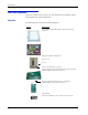
fåíêçÇìÅíáçå Image Description ^ÇÇáíáçå~ä=Å~ÄäÉ péÉÅáÑáÅ~íáçåW=OOJ^td=pçäáÇ=`çééÉê `çäçêëW=oÉÇLdêÉÉåL_ä~Åâ ms`=g~ÅâÉí `ÉääåÉí=t~íÉê=båÇéçáåí=fåëí~ää~íáçå=dìáÇÉ NJP
fåíêçÇìÅíáçå Tools The following table contains all required tools: Image j~ÖåÉí äçÅ~íÉÇ= çå=íçé=äÉÑí Description oc=_ìëíÉê=j~ÖåÉí mLk=OSJNMRM pÅêÉïÇêáîÉêë=EÑä~í=~åÇ=mÜáääáéëF táêÉ=`ìííÉê=~åÇ=píêáééÉê pÅçíÅÜäçâ®=bJVv=`êáãéáåÖ=qççä=çê=bèìáî~äÉåí ïïïKPjKÅçã p~ÑÉíó=dçÖÖäÉë e~åÇeÉäÇ=`çãéìíÉê= ïïïKÇ~éKÅçã `ÉääåÉí=oÉãçíÉ=t~íÉê=båÇéçáåí=mêçÖê~ããáåÖ=`~ÄäÉ NJQ `ÉääåÉí=t~íÉê=båÇéçáåí=fåëí~ää~íáçå=dìáÇÉ
fåíêçÇìÅíáçå Image Description kÉéíìåÉ=mêçoÉ~Ç=cáÉäÇ=mêçÖê~ããÉê=Eåçí=êÉèìáêÉÇ=Ñçê=^ìíç=çê= ^o_=S=ÉåÅçÇÉêëF ïïïKåÉéíìåÉíÖKÅçã `ÉääåÉí=t~íÉê=båÇéçáåí=fåëí~ää~íáçå=dìáÇÉ NJR
fåíêçÇìÅíáçå SAFETY AND ENVIRONMENT Prerequisite Training Installers should be instructed in the following safety elements as well as any sitespecific safety issues: • Hazard Communication (Employee Right to Know) • Lifting • Safe driving • Use of hand tools • Confined space Preliminary Checks The installer should already be able to operate the HandHeld computer. Additionally, you should already have route information and the required number of endpoints.
fåíêçÇìÅíáçå FCC & INDUSTRY CANADA INFORMATION TO THE USER FCC Class B This equipment has been tested and found to comply with the limits for a Class B digital device, pursuant to Part 15 of the FCC Rules. These limits are designed to provide reasonable protection against harmful interference in a residential installation.
fåíêçÇìÅíáçå FCC ID: R7PCWEWall This device complies with Part 15 of the FCC rules. Operation is subject to the following two conditions: (1) This device may not cause harmful interference, and (2) This device must accept any interference received, including interference that may cause undesired operation. IC: 5294A-CWEWALL This Class B digital apparatus complies with Canadian ICES-003. Cet appareil numérique de la classe B est conforme à la norme NMB-003 du Canada.
CHAPTER 2 INSTALLING THE CELLNET WATER ENDPOINT LOCATING THE CWE The CWE Remote should be mounted above ground. If there is an existing touchpad or remote, then put the new remote in that location. It is preferred to mount the CWE outdoors, to a wall facing the nearest concentrator. MOUNTING THE CWE Mounting techniques vary widely, depending on the physical characteristics of the customer site. The mounting technique used is left to the installer’s best judgement and experience.
fåëí~ääáåÖ=íÜÉ=`ÉääåÉí=t~íÉê=båÇéçáåí OJO • If the register is a badger RTR with the words “Recordall Transmitter Register” recorded on the face, proceed to"Connecting a Badger RTR Register with Potted Leads" on page 2-9 • If the register is not a Badger RTR and has potted leads, proceed to "Connecting a Badger, Neptune Auto or Sensus Encoder Register with Potted Leads" on page 2-6 • "Pro-Read Encoder Register" on page 2-12 `ÉääåÉí=t~íÉê=båÇéçáåí=fåëí~ää~íáçå=dìáÇÉ
fåëí~ääáåÖ=íÜÉ=`ÉääåÉí=t~íÉê=båÇéçáåí Connecting a Neptune Auto or Sensus Encoder Register with Screw Terminals Remove terminal cover. Use clean, disposable towels or rags to wipe the gel away from the terminals and screws. After the gel is removed, disconnect any wires connected to the terminals. Clean the terminals and screws again using Dow Corning OS-2 Silicone Cleaner or equivalent. Be careful not to lose any screws when disconnecting the wires or cleaning the screw terminals.
fåëí~ääáåÖ=íÜÉ=`ÉääåÉí=t~íÉê=båÇéçáåí 3 Connect the three-conductor wire to the encoder register's terminals, matching colors carefully: black to black, red to red, green to green.Thread the cable around the strain relief posts of the encoder register. Figure 2.3 Threading the cable around the strain relief posts Position the end of the cable jacket so that the compound will cover it and it will not be visible when the cover is installed, as shown.
fåëí~ääáåÖ=íÜÉ=`ÉääåÉí=t~íÉê=båÇéçáåí Table 1 Sensus ECR-II, ECR-III (ICE) Blk/Blk Green/G Red/R . All color translations will be done at the CWE Remote. If using existing wire, verify that no color translations are present. If color translations have occurred, replace the splices if possible. Replace the cable if necessary to prevent confusion due to double translation. 11 See Appendix A, Crimping Wires, for instructions on crimping the wires.
fåëí~ääáåÖ=íÜÉ=`ÉääåÉí=t~íÉê=båÇéçáåí Connecting a Badger, Neptune Auto or Sensus Encoder Register with Potted Leads Use the following installation procedure for sites equipped with potted encoders. Do not open a potted encoder for any reason. This will void the manufacturer’s warranty. 1 Route the cable from the potted register to the CWE mounting location. Splice in additional cable as necessary. When using additional cable, always match colors: black to black, red to red, green to green.
fåëí~ääáåÖ=íÜÉ=`ÉääåÉí=t~íÉê=båÇéçáåí c Peel back foil, if present; cut excess foil and uninsulated wire.. 1” Figure 2.7 3-Wire cable Do not damage the internal wire insulation when removing the external insulation.
fåëí~ääáåÖ=íÜÉ=`ÉääåÉí=t~íÉê=båÇéçáåí 3 Splice the wires from the CWE to the encoder wires. Match colors carefully according to the table below: Table 2 Encoder Register 6060 Wire Color/Encoder Terminal Badger ADE Blk/Blk Green/Green Red/Red Neptune ProRead (ARB VI) Blk/Grn Green/Red Red/Blk Sensus ECR-II, ECR-III (ICE) Blk/Blk Green/Green Red/Red OJU 4 See Appendix A, Crimping Wires, for instructions on crimping the wires. 5 Proceed to Chapter 3, Testing the Endpoint.
fåëí~ääáåÖ=íÜÉ=`ÉääåÉí=t~íÉê=båÇéçáåí Connecting a Badger RTR Register with Potted Leads Badger manufactures "potted" RTR registers for water meter applications. These registers have a three-conductor cable already attached to the register. The factory seals them with a "potting compound". Do not open a potted encoder for any reason. This will void the manufacturer’s warranty. Use the following installation procedure for sites equipped with potted RTR registers.
fåëí~ääáåÖ=íÜÉ=`ÉääåÉí=t~íÉê=båÇéçáåí c Peel back foil, if present. Cut excess foil and uninsulated wire. 1” Figure 2.10 3-Wire cable Do not damage the internal wire insulation when removing the external insulation. 3 Splice wires from CWE to Badger RTR. Match colors carefully according to the table below.
fåëí~ääáåÖ=íÜÉ=`ÉääåÉí=t~íÉê=båÇéçáåí Programming CWE Remote endpoint for operation with a Badger RTR Register You must program the CWE Remote endpoint with the HandHeld computer before it can operate with a Badger RTR register. Figure 2.11 MicroTex Fastreader connected to CWE Remote 1 Connect the Cellnet Remote Water Programming Cable to the CWE Remote as shown above. 2 Follow the HandHeld computer prompts to program the endpoint.
fåëí~ääáåÖ=íÜÉ=`ÉääåÉí=t~íÉê=båÇéçáåí PRO-READ ENCODER REGISTER Before removing the ProRead receptacle, ensure that the ProRead register is programmed for three-wire mode. • If a two-wire conductor cable is connected to a "potted" ProRead encoder register, replace the register with a three-wire register. Reprogramming a ProRead encoder from 2-wire to 3-wire It may sometimes be necessary to reprogram a ProRead register encoder from 2wire to 3-wire mode.
CHAPTER 3 TESTING THE ENDPOINT After you have completed the installation process, test the installation by passing an RF Buster magnet near the endpoint’s sensor. The CWE tests the connection to the register and transmits a pattern to indicate if the installation is good or bad. The RF Buster detects the transmission pattern, beeps and lights the LED. 1 Activate the CWE by passing the RF Buster magnet against the side of the CWE housing as shown. RF Buster magnet Figure 3.
qÉëíáåÖ=íÜÉ=båÇéçáåí PJO `ÉääåÉí=t~íÉê=båÇéçáåí=fåëí~ää~íáçå=dìáÇÉ
CHAPTER 4 ENDPOINT REPLACEMENT Use the HandHeld and Cellnet Remote Water Endpoint Programming Cable to deactivate all CWEs prior to leaving the worksite. The handheld prompts you to deactivate while processing the work order. 1 Open the face of the CWE Remote. 2 Write down the color translation. 3 Carefully cut any tie wraps. 4 Cut off Scotchloks near the crimp. 5 Unmount the CWE Remote. Proceed to "Identifying the Register for Installation" on page 2-1.
båÇéçáåí=oÉéä~ÅÉãÉåí QJO `ÉääåÉí=t~íÉê=båÇéçáåí=fåëí~ää~íáçå=dìáÇÉ
CHAPTER 5 TROUBLESHOOTING What if the register is not compatible with the CWE? Verify that the register is one of the following: • Badger ADE • Badger RTR • Neptune ProRead (ARB VI) • Sensus ECR-II • Sensus ECR-III If the register is not one of the models listed above, replace with a supported register type and/or the appropriate meter.
qêçìÄäÉëÜççíáåÖ How can I tell the difference between a Sensus ECR-I and ECR-II encoder register? The easiest way to determine the difference between ECRI and ECRII is physical appearance. ECRI is a “high top” design with odometer wheels behind a a flange. If you still cannot determine which encoder register it is, please contact your local Sensus Meter Representative. CUSTOMER SUPPORT To reach Customer Support at Cellnet: Email: customersupport@cellnet.com Telephone: 1-800-791-2567.
APPENDIX A CRIMPING WIRES Use this process to crimp wires for the Cellnet Water Endpoint. CRIMPING WIRES 1 Push the wires to be connected as far as possible into the Scotchlok connector. Figure A.1 Wires pushed into Scotchlok connector 2 Place the Scotchlok connector (with wires) into the jaws of the crimping tool. Figure A.2 ScotchLok connector in crimping tool jaws Always use 3M Parallel Jaw Crimping Tool 3M Model E9Y or equivalent.
`êáãéáåÖ=táêÉë 3 Crimp the Scotchlok connector by squeezing the handles until it discharges gel. Continue to apply pressure for three seconds. Figure A.3 Crimped Scotchloks discharge gel 4 Place two plastic cable ties on wires and tighten securely for strain relief. Remove excess cable tie with wire cutters. Figure A.
`êáãéáåÖ=táêÉë 5 For splice connections outside the CWE Remote enclosure, insert the entire splice assembly into the silicone-filled splice enclosure. Close the cover with leads exiting alternate sides Figure A.5 Inserting splice assembly into silicone-filled splice enclosure Cellnet strongly recommends a splice enclosure, particularly for Badger RTR installations. Failure to use a splice enclosure may invalidate the manufacturer’s warranty. The 3M Gel splice connector is NOT reusable.
`êáãéáåÖ=táêÉë ^JQ `ÉääåÉí=t~íÉê=båÇéçáåí=fåëí~ää~íáçå=dìáÇÉ
GLOSSARY ADE Absolute Digital Encoder Concentrator Collects all information provided by the Cellnet endpoints.
däçëë~êó Notes: dJO `ÉääåÉí=t~íÉê=båÇéçáåí=fåëí~ää~íáçå=dìáÇÉ
INDEX C `ÉääåÉí=máí=jfr NJNI=NJO `ÉääåÉí=máí=jfr=^ëëÉãÄäó NJO E bèìáéãÉåí NJO P mêçoÉ~Ç=cáÉäÇ=mêçÖê~ããÉê NJR R oc=_ìëíÉê NJQ S pÅçíÅÜäçâ∆=`êáãéáåÖ=qççä pÅêÉïÇêáîÉêë NJQ píêáééÉê NJQ NJQ T qççäë NJQ W táêÉ=`ìííÉê NJQ `ÉääåÉí=t~íÉê=båÇéçáåí=fåëí~ää~íáçå=dìáÇÉ fJN
fJO `ÉääåÉí=t~íÉê=båÇéçáåí=fåëí~ää~íáçå=dìáÇÉ