Certification Exhibit FCC ID: R7PEC6R1S3 IC: 5294A-EC6R1S3 FCC Rule Part: 15.247 IC Radio Standards Specification: RSS-210 ACS Project Number: 14-0364 Manufacturer: Landis+Gyr Technology, Inc. Model: GPR2 5015 B.U.
GPR Installation Guide Publication: 98-1135 Rev AB LANDIS+GYR CONFIDENTIAL INFORMATION
Limitation on Warranties and Liability Information in this document is subject to change without notice. This manual or any part of it thereof may not be reproduced in any form unless permitted by contract or by written permission of Landis+Gyr.
Table of Contents Chapter 1: Pre-Installation . . . . . . . . . . . . . . . . . . . . . . . . . . . . . . . . . . . . . . . . . . . . . . . . . . . . . . . . . . . 7 Before You Begin . . . . . . . . . . . . . . . . . . . . . . . . . . . . . . . . . . . . . . . . . . . . . . . . . . . . . . . . . . . . . . . . . . . . . . . . 7 Safety Overview . . . . . . . . . . . . . . . . . . . . . . . . . . . . . . . . . . . . . . . . . . . . . . . . . . . . . . . . . . . . . . . . . . . . . . . . .
Table of Contents Landis+Gyr Meter Preparation . . . . . . . . . . . . . . . . . . . . . . . . . . . . . . . . . . . . . . . . . . . . . . . . . . . . . . . . . . . . . . . . .33 Installing Index Face Mount Dial Wheels on Metal Pointer Indexes . . . . . . . . . . . . . . . . . . 35 Installing Balanced Dial Wheels on Plastic Pointer Indexes . . . . . . . . . . . . . . . . . . . . . . . . . 37 GPR Direction . . . . . . . . . . . . . . . . . . . . . . . . . . . . . . . . . . . . . . . . . . . . . . . . . . .
Landis+Gyr Table of Contents Chapter 8: Dresser Roots Installation . . . . . . . . . . . . . . . . . . . . . . . . . . . . . . . . . . . . . . . . . . . . . . . . . . 99 Meter Module Retrofit . . . . . . . . . . . . . . . . . . . . . . . . . . . . . . . . . . . . . . . . . . . . . . . . . . . . . . . . . . . . . . . . . . . 99 Validated Meter Index Part Numbers . . . . . . . . . . . . . . . . . . . . . . . . . . . . . . . . . . . . . . . . . . . . . . . . . . . . . . . 100 Dial Wheel Installation . . . .
Blank Page
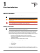
1 Pre-Installation Before You Begin This text contains the symbols which are explained below. A U NOTE: Notes provide important information about products and installation. CAUTION: Cautions provide information that you must read to avoid making relatively moderate errors. WARNING: Warnings provide special, must-read information. If you ignore a warning you may create a safety hazard, omit essential data, or make a critical error.
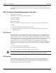
Chapter 1 - Pre-Installation Landis+Gyr understand that their supervisor’s responsibility does not relieve them from their individual responsibility to perform the work safely and to follow all safety rules and procedures applicable to their work. FCC & Industry Canada Information to the User Manufacturer: Landis+Gyr Model Name: American Large Diaphragm GPR FCC ID: R7PEC6R1S3 IC: 5294A- EC6R1S3 Module Model: GPR2 This device complies with Part 15 of the FCC rules.
Landis+Gyr Chapter 1 - Pre-Installation Industry Canada This device complies with Industry Canada license-exempt RSS standard(s). Operation is subject to the following two conditions: (1) this device may not cause interference, and (2) this device must accept any interference, including interference that may cause undesired operation of the device. Le présent appareil est conforme aux CNR d'Industrie Canada applicables aux appareils radiovexempts de licence.
Chapter 1 - Pre-Installation Landis+Gyr Required Installation Tools Table 1-1. Typical Gas Meter Module Installation Tool List Torx Pin Head Driver, T10 Phillips Screwdriver, #2 Flat-tip Screwdriver, 3/16 inch x 4 inch Flat-tip Screwdriver, 1/4 inch x 5 inch Phillips Screwdriver, #0, precision Torque Driver / Wrench, 0.5 inchpounds to 20 foot-pounds Torx Pin Head Driver, T15 5/16 Combination Wrench Wire Brush Awl, Heavy duty Scraper, Brass, 1.25 inch wide Figure 1 - 1.
Landis+Gyr Chapter 1 - Pre-Installation American Meters Required Materials Index Cover Kits Select one based on index type or meter size. Table 1-2. American Meter Index Cover Mini Switch Kits Description Part Number Index Cover Assy, Am AL800, 2-Way SSP 40-2474 Index Cover Assy, AL800 100ft, 2-Way SSP 40-2475 Index Cover Assy, Am Res AL425 2-Way SSP 40-2473 Dial Wheels Select one wheel based on index type. Table 1-3.
Chapter 1 - Pre-Installation Landis+Gyr GPR + Brackets Kits Select one based on GPR location on meter. Table 1-4. American GPR + Brackets Kits Description Part Number Kit, GPR Installation, American Large Diaphragm, Alternative Orientation 45-1189 Kit, GPR Installation, American Large Diaphragm, Behind Index 45-1190 Kit, American Large Diaphragm Alternative Orientation GPR 45-1193 Figure 1 - 3.
Landis+Gyr Chapter 1 - Pre-Installation Table 1-7. Kit, American Large Diaphragm Alternative Orientation GPR, #45-1193 Description Part Number Bracket, GPR, C & I Gas American, Alternate Orientation 28-1443 GPR Assembly w/ Universal Bracket 45-1185 Hardware Kit, American Large Diaphragm, 2-Way 45-1203 NOTE: Bracket, 28-1443, can be used in either front-right or back-left orientations. Table 1-8.
Chapter 1 - Pre-Installation Landis+Gyr Figure 1 - 4. GPR with American Large Diaphragm brackets and hardware Figure 1 - 5. Hardware Kit #45-1203 for Index Cover and Bracket Figure 1 - 6. Part No. 29-1300 0.030” thick Shim for front or back mount Dial Wheel Installation 14 NOTE: Individual components and kits may be ordered for installing the GPR with American large diaphragm meters.
Landis+Gyr Chapter 1 - Pre-Installation Rockwell Meters Required Materials Index Cover Kit Table 1-11. Rockwell Large Diaphragm Meter GPR Index Cover Kit Description Part Number Index Cover Assy, Rock R750, 2-Way SSP 40-2470 Dial Wheel Table 1-12. Rockwell Large Diaphragm Meter GPR Dial Wheel A Description Part Number Dial Wheel, Index Back Mount, Epoxy 40-1743 CAUTION: Part numbers are subject to change. Contact the Landis+Gyr Supply Chain for the latest part numbers. Figure 1 - 7.
Chapter 1 - Pre-Installation Landis+Gyr Table 1-13. GPR Installation Kit for Rockwell 750 Large Diaphragm Meter #45-1186 Kit, Rockwell Large Diaphragm Index Cover Hardware 45-1169 GPR Assembly w/ Universal Bracket 45-1185 Table 1-14. Kit, Rockwell Large Diaphragm Index Cover Hardware #45-1169 Description Part Number Cup, Security, Wedge LOC 22-0281 Screw, 5/16 - 18x1.25 LG, SS, FH 22-1358 Seal, Tamper, MM, RKWL, Cover 22-0275 Tie Wrap, 3.9 inch, UV, Nylon, Black 30-0502 Table 1-15.
Landis+Gyr Chapter 1 - Pre-Installation Figure 1 - 9. Part No. 29-1300 0.030” thick Shim for front or back mount Dial Wheel Installation NOTE: GPR Cover should not be attached until GPR is fully mounted. Figure 1 - 10. GPR with Rockwell Large Diaphragm Universal Hardware NOTE: Individual components and kits may be ordered for installing the GPR with Rockwell large diaphragm meters. Schlumberger Meters Required Materials Index Cover Kit Table 1-16.
Chapter 1 - Pre-Installation Landis+Gyr Figure 1 - 11. Schlumberger GPR Index Cover NOTE: GPR switch cable color may vary from that shown in photos. GPR + Brackets Kit As part of the Required Materials, part number 45-1187, the Schlumberger Large Diaphragm GPR Kit, includes the following components: • 45-1185, GPR Assembly w/ Universal Bracket • 45-1171 Schlumberger Large Diaphragm Index Cover Hardware Kit. Table 1-18.
Landis+Gyr Chapter 1 - Pre-Installation Table 1-20. GPR Assembly w/ Universal Bracket #45-1185 Description Part Number Washer, #10, EXT LK, SS 22-0119 Kit, Hardware, Wall Mount Cover (GPR Cover Mounting Kit) 45-1042 NOTE: Individual components and kits may be ordered for installing the GPR with Schlumberger large diaphragm meters. Figure 1 - 12. Schlumberger Large Diaphragm Index Cover Hardware (Part# 45-1171) NOTE: GPR Cover should not be attached until GPR is fully mounted.
Chapter 1 - Pre-Installation Landis+Gyr Index Cover Kit Table 1-21. Sprague Large Diaphragm Meter GPR Kit Description Part Number Index Cover Assy, Sp 1000, 2-Way SSP 40-2472 Dial Wheel Select one based on index type. Table 1-22. GPR Dial Wheels Description Part Number Dial Wheel, Balanced, C+I, Epoxy 40-1538 Dial Wheel, Index Face Mount, Epoxy 40-1742 Figure 1 - 14. Sprague 1000 GPR Index Cover Assembly Figure 1 - 15.
Landis+Gyr Chapter 1 - Pre-Installation GPR + Brackets Kit As part of the Required Materials, part number 45-1188, Sprague Large Diaphragm GPR Kit, includes the following components: • 45-1185, GPR Assembly w/ Universal Bracket • 45-1114, Sprague Large Diaphragm Index Cover Hardware Kit Figure 1 - 16. 0.030 Shim for Magnetic Dial Wheel Installation, Part # 29-1300 Table 1-23.
Chapter 1 - Pre-Installation Landis+Gyr Figure 1 - 17. Sprague Large Diaphragm Hardware Kit #45-1114 for Index Cover Table 1-25.
Landis+Gyr Chapter 1 - Pre-Installation Rotary Required Materials For rotary meters a cable, GPR, and bracket kit are needed. Table 1-26. Rotary Gas Meter Module Installation Tool List Torx Pin Head Driver, T10 Flat-tip Screwdriver, 1/4 inch x 5 inch Torx Pin Head Driver, T15 Wire Cutter\Stripper for 19-26-AWG solid conductor wire Flat-tip Screwdriver, 3/16 inch x 4 inch Badger Field Splice Kit 62084-001 Torque Driver \ Wrench, 0.
Chapter 1 - Pre-Installation Landis+Gyr Dresser Roots Required Materials Meter Adapter Kit (Ordered from GE) Table 1-29. GE AMR Adapter Kit Part Number (GE) Description 45-2476 Adapter Kit, Dresser Roots, GE AMR Gridstream Module Table 1-30. Gridstream American Residential Module Part Number Description 26-1307 ResGas, Endpoint, American Long Pin Index Table 1-31.
2 Index Cover Pulser Install and Operation Start Up Introduction The index cover pulser has a single channel. The channel is for measuring gas volume pulses. The pulser is type Form-C. Before starting a module in for the first time, double check the following: • The index cover is properly installed to the meter index. • The GPR module is properly mounted to the meter. NOTE: The output of the pulser is to be connected to Channel B on the GPR.
Chapter 2 - Index Cover Pulser Install and Operation Start Up Landis+Gyr Interface to a Single Form-C Volume Output The interface to a single Form-C volume pulse output from the index cover is shown in the figure and table below. Figure 2 - 2.
Landis+Gyr Chapter 2 - Index Cover Pulser Install and Operation Start Up NOTE: The cable connector is shown downside up. Figure 2 - 3. Cable to GPR Connection for a Single Form-C Volume Input Table 2 - 1.
Chapter 2 - Index Cover Pulser Install and Operation Start Up Landis+Gyr Start the GPR Operation In Install Mode By now, the GPR should be fully mounted without it's cover (Rockwell meter shown for reference): Figure 2 - 4. Mounted GPR The GPR module, as received from the contract manufacturer, should have the correct Network LAN ID and CRC numbers already configured. The GPR, when installed for the first time, will start operation in Install Mode.
Landis+Gyr Chapter 2 - Index Cover Pulser Install and Operation Start Up Figure 2 - 5. Pulse Interface Cable's Shrink Tubing Must Route Through GPR Strain Relief Slot 9. Install the GPR cover using the four security Torx screws included with the GPR. The cover must be installed with the gasket tab inserted into the strain relief slot located at the bottom left corner of the GPR enclosure as shown in the following photos. Figure 2 - 6. GPR Cover Gasket Tab and Cover Strain Relief Slot 10.
Chapter 2 - Index Cover Pulser Install and Operation Start Up Landis+Gyr Figure 2 - 8.
3 American GPR Index Cover & GPR Install American Index Cover & and Gas Module Removal Index Cover Tamper Seal Base Plate with Tamper Seal Towers Figure 3 - 1. American Large Diaphragm Meter Meter Preparation 1. Remove the tamper seals, screws, and index cover assembly from the meter. 2. If the meter has an existing Commercial Gas Module, perform the following steps. A. Remove the index cover tamper seals. B. Remove the module bracket tamper seals. Remove Bracket Tamper Seals Figure 3 - 2.
Chapter 3 - American GPR Index Cover & GPR Install Landis+Gyr Remove Tamper Seals Figure 3 - 3. Remove Index Cover and Module Bracket Tamper Seals C. Remove the index cover fasteners. If needed, use a 5/16 inch combination wrench to loosen the index cover front bolt. Figure 3 - 4. Remove Index Cover Fasteners D. Remove the module bracket fasteners and carefully disconnect the module and index cover assembly from the meter. E.
Landis+Gyr Chapter 3 - American GPR Index Cover & GPR Install Figure 3 - 5. Cover Gasket and Base Plate with Optional Tamper Cup & Seal Cover Tamper Seal Location Serial/Power Connector Figure 3 - 6. Commercial Module Cover Removed 4. Swipe each end of the module with an RF Buster or magnet to force the module to save meter data to non-volatile memory. Remove the Commercial Gas Module tamper seals, screws, and cover. Disconnect the battery. 5.
Chapter 3 - American GPR Index Cover & GPR Install Landis+Gyr Figure 3 - 7. Remove Index Cover Tamper Seals and Screws 2. Gently push the Badger dial wheel toward the front of the index cover and away from the index dial pointer. Lift the index out of the cover. Figure 3 - 8. Disengage Badger Dial Wheel from Index; Remove Index from Cover 3. Inspect the index and replace it if any of the following conditions exists: U • Pointers are loose on their shafts.
Landis+Gyr Chapter 3 - American GPR Index Cover & GPR Install Installing Index Face Mount Dial Wheels on Metal Pointer Indexes U WARNING: For Index Face Mount Dial wheels with alignment slots, the wheels must be installed so that the alignment slots on each wheel half are on top as shown in the next figure. Figure 3 - 9.
Chapter 3 - American GPR Index Cover & GPR Install Landis+Gyr Figure 3 - 11. Slide Screw-bearing Wheel Half Over Index Proving/Test Pointer Tip 4. Position the bottom wheel half against the back of the index pointer. Use a small Phillips-type screwdriver and turn each screw a few turns until they begin to thread into the bottom wheel half. Do not tighten the screws. Figure 3 - 12. Thread Screws into Bottom Wheel Half 5. Insert the 0.
Landis+Gyr Chapter 3 - American GPR Index Cover & GPR Install Figure 3 - 13. Insert 0.030 inch thick Shim and alternately tighten the Dial Wheel Screws to 3.5 inch-pounds (± 0.50 inch-pounds). U WARNING: To avoid damaging the index pointer and dial wheel, take care not to over-tighten the set screws. Figure 3 - 14. Index Face Mount Dial Wheel Installed 6. Verify that the dial wheel rotates freely without rubbing the index surface.
Chapter 3 - American GPR Index Cover & GPR Install Landis+Gyr Figure 3 - 15. Top View - Balanced Wheel With Screws Backed Out Figure 3 - 16. Bottom View - Balanced Wheel 2. Position the Balanced dial wheel over the plastic index proving/test pointer as shown in the following figures. The bottom of the dial wheel is slotted so that it may only be installed with the slot in the same direction as the index pointer. 3. Insert the 0.030” thick shim beneath the dial wheel.
Landis+Gyr Chapter 3 - American GPR Index Cover & GPR Install physically contact the index face or other pointers on the index. If contact occurs, the index should be replaced with an approved index. 7. Remove the shim and verify that the wheel rotates freely while remaining level with the index surface. Figure 3 - 18. Balanced Dial Wheel Installed Installing Index Into Index Cover 1.
Chapter 3 - American GPR Index Cover & GPR Install Landis+Gyr Figure 3 - 20. Insert the Index At an Angle To Clear Wires and Switch During Installation 3. As the index passes by the wires toward the switch, gently rotate the index into its normal mounting position. Figure 3 - 21. Position Index In Normal Mounting Location 4. From the hardware kit, install the two smaller tamper cups, washers, and screws as shown in the following photos.
Landis+Gyr Chapter 3 - American GPR Index Cover & GPR Install NOTE: Cable color may vary from that shown in photos. Figure 3 - 23. Install Index Screws and Tamper Seals Figure 3 - 24. Balanced Dial Wheel on Plastic Pointer Index GPR Direction The GPR must face away from nearby walls and should be installed in a location unobstructed by gas pipes. Refer to "American Changing GPR Orientation" on page -43 for instructions.
Chapter 3 - American GPR Index Cover & GPR Install Landis+Gyr GPR Mounting 1. Using two #12-24 x 1/2 inch screws (part# 22-0185), install the GPR Mini Switch cover assembly as shown in the following photographs. A CAUTION: Check the index cover switch cable assembly for nicks, abrasions, or any damage prior to installing the assembly onto the meter. 2. Install a new index cover gasket as required. Tighten the screws to 20 inch-pounds (± 5 inchpounds. Figure 3 - 26.
Landis+Gyr Chapter 3 - American GPR Index Cover & GPR Install Figure 3 - 28. GPR at C enter Rear - Using 28-1441Bracket Figure 3 - 29. Final Installation American Changing GPR Orientation The GPR must face away from nearby walls. The GPR should be installed in a location unobstructed by gas pipes. Different mounting options are shown in the following photographs. Choose a mounting option before attaching battery and GPR cover. Figure 3 - 30.
Chapter 3 - American GPR Index Cover & GPR Install Landis+Gyr Figure 3 - 31. GPR at Right Rear - Using 28-1440 Bracket Figure 3 - 32. GPR at C enter Rear - Using 28-1441Bracket 1. Lay the GPR face down. Remove the two screws and washers holding the two brackets together as shown in Figure 3 - 33. Figure 3 - 33. GPR Bracket Disassembly 2. Determine the appropriate GPR direction. 3. Install the two screws and lock washers. Tighten the screws to 30 inch-pounds (+/- 2 inchpounds).
Landis+Gyr Chapter 3 - American GPR Index Cover & GPR Install gas pipe. The maximum cable length between the Mini Switch and GPR must not exceed 200 feet. A Installation Guide CAUTION: In a remote GPR Mounting environment, Pipe Bracket Kit 45-0080 may be used to install the GPR on suitable plumbing pipes.
Chapter 3 - American GPR Index Cover & GPR Install 46 98-1135 Rev AB Landis+Gyr Installation Guide
4 Rockwell GPR Index Cover & GPR Install Rockwell Index Cover & Gas Module Removal Meter Preparation 1. Remove the tamper seals, screws, and index cover assembly from the meter. If there is no Commercial Gas Module connected to the meter, it will appear as below. Index Cover Screws Figure 4 - 1. Rockwell Large Diaphragm Meter Index Cover Front And Rear Views Index Cover Tamper Seals Figure 4 - 2. Remove Index Cover Tamper Seals, Screws. and Index Cover 2.
Chapter 4 - Rockwell GPR Index Cover & GPR Install Landis+Gyr Figure 4 - 3. Center Dial and Offset Dial Mount Rockwell Commercial Index Covers NOTE: There are two types of Rockwell Commercial index covers. Shown at left in Figure 4 - 3 is the Center Dial Mount and at right is the Offset Dial Mount. Both types may be removed from the meter in the same manner as shown in the next illustration. Figure 4 - 4. Remove Module Bracket Tamper Seals, Screws, and Gas Module Assembly 3.
Landis+Gyr Chapter 4 - Rockwell GPR Index Cover & GPR Install Module Cover Tamper Seal Location Serial/Power Connector Figure 4 - 6. Commercial Module Cover Removed 4. Swipe each end of the module with an RF Buster or magnet to force the module to save meter data to non-volatile memory. Remove the Commercial Gas Module tamper seals, screws, and cover. Disconnect the battery. 5. The Commercial Gas Module must be disassociated from the meter. A.
Chapter 4 - Rockwell GPR Index Cover & GPR Install Landis+Gyr Installing Back Mount Dial Wheels Figure 4 - 7. Alignment Slots Top of Each Wheel Half 1. Insert one screw into the notched dial wheel half. 2. If the dial wheel halves have alignment slots, position them so that the slots on each half are aligned. Turn the screw until it begins to thread into the threaded bottom wheel half as shown in the following figures. Figure 4 - 8.
Landis+Gyr Chapter 4 - Rockwell GPR Index Cover & GPR Install Figure 4 - 10. Shim insertion 7. Press the dial wheel upward against the shim. The wheel must be held flush with the shim while tightening the screws. 8. Tighten each screw a few turns at a time so that the two wheel halves remain parallel with each other, keeping the dial wheel hole centered on the shaft. Tighten the screws to 3.5 inch-pounds ± 0.5 inch-pound).
Chapter 4 - Rockwell GPR Index Cover & GPR Install Landis+Gyr Figure 4 - 11. Index Drive Shaft Arm Alignment If the index must be replaced or if the index has been removed from the frame, install the index to the frame and tighten the 8-32 x 3/16 inch screws to 10.5 inch-pounds (± 1.5 inch-pound). A CAUTION: The index MUST be installed with the mounting bracket inside the index back plate, as shown in the following photograph. Index to Index Frame Screws: 10.
Landis+Gyr Chapter 4 - Rockwell GPR Index Cover & GPR Install GPR Direction The GPR must face away from nearby walls and should be installed in a location unobstructed by gas pipes. Refer to "Rockwell Changing GPR Orientation" on page -55 for instructions. Refer to Appendix A, GPR Waterproofing for waterproofing guidelines before attaching connectors. Photos are for reference only: GPR cover and battery should not be connected until Chapter 2.
Chapter 4 - Rockwell GPR Index Cover & GPR Install Landis+Gyr Figure 4 - 15. Tighten Bracket Screws 15 to 20 inch-pounds U NOTE: Sensus (Rockwell/Equimeter) does not specify nor recommend a gasket between the index cover and meter head. The meter parts list and assembly diagram do not include an index cover gasket.
Landis+Gyr Chapter 4 - Rockwell GPR Index Cover & GPR Install Tamper Cup and Seal GPR Cable Routed Beneath GPR Bracket Figure 4 - 17. Install a Seal In Each Tamper Cup Cable attached to bracket with zip tie Tamper Seal Figure 4 - 18. Attach Cable to Bracket with Black Zip Tie Figure 4 - 19. GPR and Index Cover Installed in Both Orientations Rockwell Changing GPR Orientation The GPR must face away from nearby walls and toward the nearest MCC or Concentrator.
Chapter 4 - Rockwell GPR Index Cover & GPR Install Landis+Gyr Figure 4 - 20. GPR Facing Forward-Center Figure 4 - 21. GPR Facing Forward-Left 1. Remove the two screws and washers holding the two brackets together as shown in Figure 4 22. Figure 4 - 22. GPR Bracket Disassembly 2. Determine the appropriate GPR direction. 3. Install the two screws and lock washers. Tighten the screws to 30 inch-pounds (+0 / -2 inchpound).
5 Schlumberger GPR Index Cover & GPR Install Schlumberger Index Cover & Gas Module Removal U WARNING: The Schlumberger/Actaris 675-1000 meter is designed so that the index may face the front or rear of the meter. Landis+Gyr only supports GPR cover use when installed: with the index facing the front of the meter where the meter inlet pipe is located at the left side of the meter. Meter Preparation 1. Remove the tamper seals, screws, and index cover assembly from the meter. 2.
Chapter 5 - Schlumberger GPR Index Cover & GPR Install Landis+Gyr Index Mounting Bracket Types Unsupported Mounting Bracket Assembly The next three figures illustrate an example of an index mounting bracket assembly NOT supported by the Schlumberger/Actaris GPR Index cover. This bracket assembly must be replaced with Itron (Schlumberger/Actaris) part number 55045404. A. Remove the index mounting bracket assembly screws as shown in the following Figure (red circles). Save the screws.
Landis+Gyr Chapter 5 - Schlumberger GPR Index Cover & GPR Install Figure 5 - 4. Index Removed from Unsupported Bracket Assembly Supported Mounting Bracket Assembly The index mounting bracket assembly shown in the next two figures, Itron (Schlumberger/Actaris) part# 55045404, is supported with the GPR index cover. A. Remove the index mounting bracket assembly screws as shown in the following figure (red circles). Save the index screws. They will be used during reassembly. Figure 5 - 5.
Chapter 5 - Schlumberger GPR Index Cover & GPR Install Landis+Gyr of mounting bracket unless the index is defective or damaged. See “Meter Preparation” on page 57 for index approval criteria. 1. Remove the original gasket material from the meter. A scraper and wire brush may be required to remove gasket material still adhering to meter mounting surfaces. 2. Swipe each end of the module with an RF Buster or magnet to force the module to save meter data to non-volatile memory. Disconnect the battery. 3.
Landis+Gyr Chapter 5 - Schlumberger GPR Index Cover & GPR Install Perform the following steps if the index must be replaced: Figure 5 - 8. Index Screw and Drive Details 1. Turn index screws (shown by red circles) counter clockwise enough to loosen and gently slide the old index screw tabs from beneath the screws using a right-to-left motion. 2. Slide the replacement index screw tabs beneath the screws using a left-to-right motion as shown in the photo at right in Figure 5 - 8. 3.
Chapter 5 - Schlumberger GPR Index Cover & GPR Install Landis+Gyr NOTE: For wheels WITHOUT alignment slots, there is no top or bottom, and there is no special consideration regarding dial wheel assembly. 3. Slide threaded wheel half beneath the rear horizontal index drive shaft. Figure 5 - 11. Slide Threaded Wheel Half Beneath the Index Drive Shaft Figure 5 - 12. Slide Threaded Wheel Half Beneath Shaft 4. Rotate the notched wheel half over the top of the shaft and insert the second screw.
Landis+Gyr Chapter 5 - Schlumberger GPR Index Cover & GPR Install 6. Press wheel lightly but evenly against the shaft snap ring located at the rear of the shaft. The dial wheel must not touch the gears on the shaft. 7. Tighten each screw a few turns at a time so that the two wheel halves remain parallel with each other, and the dial wheel hole is centered on the shaft. Tighten the screws to 3.5 inch-pounds ± 0.50 inch-pounds. U WARNING: Avoid damaging the dial wheel.
Chapter 5 - Schlumberger GPR Index Cover & GPR Install Landis+Gyr GPR Direction If at all possible, the GPR must face away from nearby walls and should be installed in a location unobstructed by gas pipes. Refer to "Schlumberger Changing GPR Orientation" on page -66 for instructions. Refer to Appendix A, GPR Waterproofing for waterproofing guidelines before attaching connectors. Photos are for reference only: GPR cover and battery should not be connected until Chapter 2.
Landis+Gyr Chapter 5 - Schlumberger GPR Index Cover & GPR Install Figure 5 - 17. Coil the Excess Cable Cable must slope down and away from cover Figure 5 - 18. Route and Attach the Excess Cable 6. Attach the excess coiled cable to the GPR bracket with a black nylon zip tie as shown in the previous figures. A CAUTION: The cable should slope downward and away from the index cover to aid the water tight strain relief in preventing water from entering the cover. Do NOT crimp or pull the cable tight. 7.
Chapter 5 - Schlumberger GPR Index Cover & GPR Install Landis+Gyr Figure 5 - 19. GPR and Index Cover Assembly Installed On a Schlumberger Large Diaphragm Meter U WARNING: The index cover switch cable assembly must not be pinched in any way, especially under the following circumstances: During index cover and cable assembly installation onto the meter. During GPR enclosure cover installation. Between the GPR and meter brackets and meter.
Landis+Gyr Chapter 5 - Schlumberger GPR Index Cover & GPR Install Figure 5 - 21. GPR Facing Right 1. Lay the GPR on its back. Remove the two screws and washers holding the two brackets together as shown in the next figure. Figure 5 - 22. GPR Bracket Disassembly 2. Determine the appropriate GPR direction. 3. Install the two screws and lock washers. Tighten the screws to 30 inch-pounds (+ / - 2 inchpounds).
Chapter 5 - Schlumberger GPR Index Cover & GPR Install 68 98-1135 Rev AB Landis+Gyr Installation Guide
6 Sprague GPR Index Cover & GPR Install Sprague Index Cover & Gas Module Removal Meter Preparation 1. Remove the tamper seals, screws, and index cover assembly from the meter. 2. If a Commercial Gas Module is present, remove the tamper seals and screws. Tamper Seal Tamper Seal Figure 6 - 1. Sprague Large Diaphragm Meter with Commercial Gas Module 3. Remove the bracket and Index Cover assembly. Take care not to damage the meter index. Figure 6 - 2.
Chapter 6 - Sprague GPR Index Cover & GPR Install Landis+Gyr Cover Tamper Seal Location Serial/Power Connector Figure 6 - 3. Commercial Module Cover Removed 4. Swipe each end of the module with an RF Buster or magnet to force the module to save meter data to non-volatile memory. Remove the Commercial Gas Module tamper seals, screws, and cover. Disconnect the battery. 5. The Commercial Gas Module must be disassociated from the meter. A.
Landis+Gyr Chapter 6 - Sprague GPR Index Cover & GPR Install Sprague Mini Switch Kit Installation U A WARNING: The Front mount dial wheel must be used with metal pointer indexes. The Balanced Dial wheel must be used on plastic pointer indexes. CAUTION: Take care not to over-tighten the set screws to avoid damaging the index pointer and dial wheel. Installing Front Mount Dial Wheels on Metal Pointer Indexes 1. Remove the index from the meter.
Chapter 6 - Sprague GPR Index Cover & GPR Install Landis+Gyr 4. Position the screw-bearing notched wheel half for installation by sliding it downward over the index proving/test pointer tip as shown in Figure 6 - 7. If present, the two alignment slots and pointer notch must be visible on top of the wheel half. Figure 6 - 7. Slide Screw-bearing Notched Wheel Half over Index Proving/Test Pointer Tip 5. Position the threaded wheel half against the rounded end of the index pointer.
Landis+Gyr Chapter 6 - Sprague GPR Index Cover & GPR Install Figure 6 - 9. Insert Shim and Alternately Tighten Screws To 1.2 inch-lbs. (±0.10 inch-lbs.) U WARNING: To avoid damaging the index pointer and dial wheels, take care not to overtighten the set screws. Figure 6 - 10. Front Mount Dial Wheel Installed 7. Verify that the dial wheel rotates freely without rubbing the index surface.
Chapter 6 - Sprague GPR Index Cover & GPR Install Landis+Gyr 8. Install the index onto the meter using the original screws that were placed aside in the first step of this process. If the index has a brass mounting bracket, tighten the index screws to a torque value of 6 - 12 inch-pounds. If the index uses a plastic mounting bracket, tighten the index screws to a torque value of 15 - 20 inch-pounds. A CAUTION: Use caution when tightening the index screws to prevent damage to the index. 9.
Landis+Gyr Chapter 6 - Sprague GPR Index Cover & GPR Install 4. Gently press the wheel against the shim with your index finger or thumb. The dial wheel must be level with the surface of the index. 5. Evenly tighten each screw to 1.2 ± 0.10 inch-pounds. U WARNING: The main index drive shaft must remain free to rotate as the wheel screws are tightened to prevent damage to the index pointer and pointer shaft Figure 6 - 15. Tighten Dial Wheel Screws to 1.2 ± 0.
Chapter 6 - Sprague GPR Index Cover & GPR Install Landis+Gyr Figure 6 - 17. Wheel Center Of Rotation Must Align With Meter Drive Center Of Rotation GPR Direction Before performing the following steps, determine the direction that the GPR will face. The GPR must face away from nearby walls and should be installed in a location unobstructed by gas pipes. Refer to "Sprague Changing GPR Orientation" on page -80 for instructions.
Landis+Gyr A Chapter 6 - Sprague GPR Index Cover & GPR Install CAUTION: Check the index cover switch cable assembly for nicks, abrasions, or any damage prior to installing the assembly onto the meter. 3. Coil the excess cable and route it behind the bracket as shown in Figure 6 - 19. Position the cable behind the bracket and secure the cable to the bracket immediately below the GPR housing with a black nylon zip tie. Do not completely tighten the zip tie.
Chapter 6 - Sprague GPR Index Cover & GPR Install Landis+Gyr Figure 6 - 21. Switch Wires Must Not Interfere With Index Pointers 5. Route the cable between the GPR bracket and top of the meter so that the cable has minimal slack protruding from behind the bracket. Verify that the cable is not pinched between the bracket and meter.
Landis+Gyr Chapter 6 - Sprague GPR Index Cover & GPR Install Figure 6 - 23. Tamper Cups and Screws 9. Verify that the magnet wheel does not contact the switch. A visible gap must exist between the wheel and switch as shown in the following photograph. Figure 6 - 24. Gap Must Be Visible Between Wheel and Switch 10. Install tamper seals into the tamper cups as shown in Figure 6 - 25. Figure 6 - 25.
Chapter 6 - Sprague GPR Index Cover & GPR Install Landis+Gyr During GPR enclosure cover installation. Between the GPR and meter brackets and meter. Sprague Changing GPR Orientation The GPR must face away from nearby walls and toward the nearest MCC or Concentrator.
Landis+Gyr Chapter 6 - Sprague GPR Index Cover & GPR Install Figure 6 - 28. GPR bracket disassembly 2. Determine the appropriate GPR direction. U WARNING: The GPR must be mounted in the forward-most position on the lower bracket so that the gas pipes do not interfere with data transmissions. Refer to the following figures for additional detail. Figure 6 - 29.
Chapter 6 - Sprague GPR Index Cover & GPR Install Landis+Gyr Figure 6 - 30. For Right-facing GPR Installs, Route Cable As Shown Figure 6 - 31.
Landis+Gyr Chapter 6 - Sprague GPR Index Cover & GPR Install Figure 6 - 32. GPR Facing Left Side of Meter Figure 6 - 33. GPR Facing Right Side of Meter 3. A Install the two screws and lock washers. Tighten the screws to 30 inch-pounds (+0 / -2 inchpounds). CAUTION: If the gas meter’s pipe route prevents installing the GPR as described in this manual, the GPR may be mounted in a remote location away from the meter such as on a wall or a gas pipe.
Chapter 6 - Sprague GPR Index Cover & GPR Install 84 98-1135 Rev AB Landis+Gyr Installation Guide
7 Electronic Pulser Installation GPR Mounting The GPR module will be mounted vertically and upright, on a pipe-mounting bracket in proximity to the pulse output of the gas meter, to minimize the cable length. This bracket can accommodate pipe diameters in the range of 2" to 3". Optionally, the GPR can be mounted on a nearby vertical surface. The cable will be routed in order to minimize its exposure to possible damage. Figure 1 below shows a typical installation. Figure 7 - 1.
Chapter 7 - Electronic Pulser Installation Landis+Gyr BOTTOM of the enclosure to prevent dirt and moisture from collecting inside the enclosure. Figure 7 - 2. Enclosure Cable Entry Notch C. Using a T-10 security Torx driver, tighten the screws to 10 in-lbs (+/- 2 in-lbs). Tighten the screws using a crisscross pattern to secure the enclosure to the bracket. Figure 7 - 3.
Landis+Gyr Chapter 7 - Electronic Pulser Installation NOTE: The four longer security Torx screws are GPR enclosure cover screws. Cover screws are included in the 40-1672 GPR kit. 2. Secure the mounting bracket with GPR to the pipe. A. Hold the GPR bracket assembly against the pipe so that the GPR is vertical and upright. B. Use the four 1/4-20 x 2 inch screws included with the bracket kit to install the two U-shaped clamps around the pipe to secure the GPR bracket to the pipe. C.
Chapter 7 - Electronic Pulser Installation Landis+Gyr Figure 7 - 5. GPR/Bracket Assembly for Vertical Pipe Installation 3. Select the appropriate cable for the meter model and pulser type onto which the GPR is to be installed. • Refer to the individual meter model and pulser type sections below for information on cable selection. 4. Route the signal transmission cable along the most direct and convenient route between the Meter and the GPR (preferably along the pipe).
Landis+Gyr Chapter 7 - Electronic Pulser Installation corrected, uncorrected, alarm, or not used. The installation information provided in this section is to help guide the user with installing a GPR module to an electronic pulser GPR Telemetry Specifications • The GPR can support two volume pulse inputs and one alarm input.
Chapter 7 - Electronic Pulser Installation Landis+Gyr Table 7 - 1.
Landis+Gyr Chapter 7 - Electronic Pulser Installation Battery Connection GPR Sensor Connector Pin #1 Figure 7 - 7. GPR Module Interior Interface to a Single Form-A Volume Output For a single Form-A volume pulse output, connect the pulser to Chan B of the GPR using the recommended cable 19-2330. The installation procedure is as follows. 1. Refer to the user manual of the pulser for information on its pulse outputs interface.
Chapter 7 - Electronic Pulser Installation Landis+Gyr Figure 7 - 8. Wiring for a Single Form-A Volume Input NOTE: The cable connector is shown downside up. Table 7 - 2.
Landis+Gyr Chapter 7 - Electronic Pulser Installation Figure 7 - 9. Cable to GPR Connection for a Single Form-A Volume Input NOTE: Battery should not be connected until GPR is fully mounted. Interface to Mil-Spec Circular Connector For pulsers that have one or two Form-A outputs through a Mil-Spec circular connector, the recommended cable for use is 19-2332. The installation procedure is as follows. 1.
Chapter 7 - Electronic Pulser Installation Landis+Gyr Figure 7 - 10. Circular Connector Wiring for Two Form-A Volume Inputs NOTE: The cable connector is shown downside up. Table 7 - 3.
Landis+Gyr Chapter 7 - Electronic Pulser Installation Table 7 - 3.
Chapter 7 - Electronic Pulser Installation Landis+Gyr Figure 7 - 11. Flying Leads Wiring for Two Form-A Volume Inputs and Alarm NOTE: The cable connector is shown downside up. Table 7 - 4.
Landis+Gyr Chapter 7 - Electronic Pulser Installation Table 7 - 4.
Chapter 7 - Electronic Pulser Installation Landis+Gyr Figure 7 - 12. Pulse Interface Cable's Shrink Tubing Must Route Through GPR Strain Relief Slot 8. Install the GPR cover using the four security Torx screws included with the GPR. The cover must be installed with the gasket tab inserted into the strain relief slot located at the bottom left corner of the GPR enclosure as shown in the following photos. Figure 7 - 13. GPR Cover Gasket Tab and Cover Strain Relief Slot 9.
8 Dresser Roots Installation Meter Module Retrofit Prior to adding the M120-1 module, follow instructions provided in the GE AMR kit (45-2476) to add the AMR adapter. This adapter is needed for attaching the proper index. Figure 8 - 1. Dresser Roots Meter w/ M120 2-way Module Figure 8 - 2.
Chapter 8 - Dresser Roots Installation Landis+Gyr Validated Meter Index Part Numbers Table 8 - 1. 01-1337 Index Parameters Index Type American Part No. Dial or “B” No. 2 Ft. Pointer 04972G072 B424 2 Ft. Pointer 04972G087 B683 Use Gridstream M120-1 Model No. 26-1307 Figure 8 - 3. M120-1 Meter Module Kit Before Installation Figure 8 - 4. M120-1 Dial Wheel and Seals Hardware Kits #45-1219 Table 8 - 2. M120-1 Dial Wheel and Seals Hardware Kit #45-1219 100 Item Number Item Name Qty.
Landis+Gyr Chapter 8 - Dresser Roots Installation Table 8 - 2. M120-1 Dial Wheel and Seals Hardware Kit #45-1219 E 22-1177 Screw, 1/4-20 x 5/8", FILH, PHH & SLH, STL 4 Dial Wheel Installation After the battery is installed, prepare to install the Dial Wheel onto the index. This step can be accomplished with the index on the meter, or on a meter index that is not installed on a meter. Figure 8 - 5.
Chapter 8 - Dresser Roots Installation Landis+Gyr the index screw hole bosses. Figure 8 - 7. Dial Wheel Pointer Slot 1. While holding the Dial Wheel, note the location of the Pointer Slot. With the index sitting on a work surface, set the Dial Wheel on the index face with the pointer slot oriented towards the pointer. Figure 8 - 8. Dial Wheel with pointer slot positioned for pointer entrance 2. Slide the Dial Wheel toward the pointer on the test hand until the Dial Wheel center contacts the pointer.
Landis+Gyr Chapter 8 - Dresser Roots Installation Figure 8 - 10. Orienting the Dial Wheel Pin before installation 4. You will feel a gentle click as the pin seats into place. Snap off or cut away the plastic connecting strip. NOTE: When the index employs square-edge pointers and the gray pin is used, there will be no connecting strip to cut away. Figure 8 - 11. Installing the Dial Wheel Pin Install the index onto the AMR adapter. Tighten screws (22-1176) to 15 +/- 2 inch-pounds. Figure 8 - 12.
Chapter 8 - Dresser Roots Installation Landis+Gyr Dial Wheel Installation Cautions When mounted dial wheels are not properly centered on index dial pointers, generally due to incorrect clip seating, negative results may include: 1. index damage 2. drag during operation 3. data read inconsistency U WARNING: Dial wheel mounting is a critical installation parameter that must be done correctly to avoid negatively impacting read data actions. Installing the Module 1.
Landis+Gyr Chapter 8 - Dresser Roots Installation Figure 8 - 14. A Screw-holding Screwdriver Will Simplify Installing This Mounting Screw 2. Install the remaining screws. If available, using a screw-holding screwdriver to install the lower right-side module mounting screw will simplify this action. Tighten the screws to a torque rating of 15 +/- 2 inch-pounds. Figure 8 - 15. Index and Gridstream M120-1 Index Cover Installed 3.
Chapter 8 - Dresser Roots Installation Landis+Gyr Figure 8 - 17. Dresser Roots meter after installation 4. Clean up debris from the retrofit and installation processes. If required by local practice, enter the appropriate information on a door hanger tag. 5. At the end of the day, the installer returns to the Cross Dock for the check-in process. The installer should also turn in inventory of unused, defective, or broken gas Meter Modules.
Landis+Gyr Chapter 8 - Dresser Roots Installation Figure 8 - 18. Main Board Reed Switch Location Field Programming and Data Collection Field programming and data collection will be done with the Endpoint Testing Manager tool. Please refer to the Endpoint Testing Manager User Guide, publication 98-1055. Battery Change Out When the battery flag (R) is set, it could be due to: • A single end-point occurrence, where the end-point may require more current to operate.
Chapter 8 - Dresser Roots Installation Landis+Gyr Figure 8 - 19. LED and Magnetic Reed Switch 2. Remove the meter module mounting screws. 3. Remove the meter module from the meter. 4. Press the snap tabs on the battery door of the module to disengage the door from the module. 5. Remove the suspect battery. 6. Apply electrical insulating compound to circuit board connections. 7. Replace the battery assembly with a new one (battery model #40-1235). 8.
Landis+Gyr Chapter 8 - Dresser Roots Installation NOTE: This module is powered by battery pack part number 40-1235. Battery pack appearance may vary. 3. Confirm that the LED at the upper right corner (as viewed from outside-front) of the module is flashing for proper operation. The LED should flash every 5 seconds for one minute. Figure 8 - 20. Module LED Table 8 - 4.
Chapter 8 - Dresser Roots Installation Landis+Gyr Figure 8 - 21. 02085 - CRC Di-Electric Grease, Silicone Novagard® G661 and Dow 4 Insulating Sealant can be used as a sealant to prevent water intrusion into the battery circuit board connections. 1. Liberally apply CRC Di-Electric Grease Compound, the compound, to the Battery Circuit Board Connector. U WARNING: Use of other sealants will void any warranty. Figure 8 - 22. Apply the Compound to the Battery Connector 2.
Landis+Gyr Chapter 8 - Dresser Roots Installation Figure 8 - 24. Apply the Compound to the Battery Connector: Cover All Contacts Ordering Information CRC Di-Electric Grease Compound Model: 02085 Description: Di-Electric Grease, Silicone, Net 3.3 oz. Manufacturer: CRC Industries Americas Group 885 Louis Drive Warminster, PA 18974-2869 Phone: (215) 674-4300 Email: info@crcindustries.com Website: http://www.crcindustries.com/ Novagard G661 is available in 5.3 ounce tubes and 1-gallon pails.
Blank Page
A GPR Waterproofing Applying Water Sealant to Circuit Board Connections CRC Di-Electric Grease Compound is recommended as a sealant to prevent water intrusion into the GPR Pulse Input and Battery circuit board connections. Figure A - 1. CRC Di-Electric Grease Compound NOTE: Novagard® G661 is also approved as an electrical sealant and is available in 5.3 ounce tubes.
Appendix A - GPR Waterproofing Landis+Gyr NOTE: CRC Di-Electric Grease Compound is electrical grade. 1. Liberally apply CRC Di-Electric Grease Compound (“the compound”) to the Battery and GPR Pulse Input circuit board connectors as shown in Figure A - 2 and Figure A - 3. GPR Pulse Input Connector Battery Connection Figure A - 2. Apply the Compound to the Battery Connector Figure A - 3. Apply the Compound to the GPR Pulse Input Connector 2.
Landis+Gyr Appendix A - GPR Waterproofing 3. Liberally apply the compound to the connectors of the GPR Pulse Input and Battery Interface cables. Force the compound into ALL holes and cover ALL electrical contacts, as shown in the following photos. NOTE: The following photos show representative cables to illustrate compound application. Figure A - 5. Apply the Compound to GPR Cable Connectors: Cover All Contacts 4.
Appendix A - GPR Waterproofing Landis+Gyr Figure A - 6. The Compound Must Cover Wires and Connectors for Watertight Seal 6. Arrange the GPR Pulse Input and Battery Interface cables as shown in Figure A - 7. The cables must not interfere with or block the GPR antenna. A CAUTION: The GPR Pulse Input cable must be inserted into the GPR enclosure strain relief slot as shown. The shrink tubing on the cable must be inserted into the strain relief slot.
Landis+Gyr Appendix A - GPR Waterproofing Figure A - 8.
Appendix A - GPR Waterproofing Landis+Gyr Ordering Information CRC Di-Electric Grease Compound Model: 02085 Description: Di-Electric Grease, Silicone, Net 3.3 oz. Manufacturer: CRC Industries Americas Group 885 Louis Drive Warminster, PA 18974-2869 Phone: (215) 674-4300 Email: info@crcindustries.com Website: http://www.crcindustries.com/ Novagard® G661 may be ordered from: Novagard Solutions® 5109 Hamilton Avenue Cleveland, OH 44114 Phone: (216) 881-3890 Facsimile: (216) 881-6977 www.Novagard.
Landis+Gyr Appendix A - GPR Waterproofing 3M Distributors http://3mcollision.com/dealers/search?zip=30022&lat=34.029613&lng=- 84.23841700000003 DKHardware.com Phone: 877-509-8040 CRL Screw-On Uncut Standard Urethane Nozzle Item # UN0Z http://www.dkhardware.com/product-11007-un0z-screw-on-uncut-standard-urethane- nozzle.html Ellsworth Adhesives W129 N10825 Washington Dr. Germantown, WI 53022 Phone: 1-877-454-9224 Website: http://www.ellsworth.com/Home.
Blank Page
B Installation in Hazardous Locations Information The following information describes and limits what can be attached to the GPR in a Division 1 location per the UL certification. 1. GPR Entity Parameters: • Uo (Voc) = 6.3 V dc • Io (Isc) = 7.34 A • Po = 5.91 W • Co (Ca) = 207 uF • Lo (La) = 43 uH 2. The output current of the GPR is limited by a resistor such that the output voltage-current plot is a straight line drawn between open-circuit voltage and short-circuit current. 3.
Appendix B - Installation in Hazardous Locations Landis+Gyr 6. Where multiples circuits extend from the GPR, they must be installed in separate cables or in one cable having suitable installation. Refer to Article 504.30(B) of the National Electrical Code (ANSI/NFPA 70) and Instrument Society of American Recommended Practice ISA RP12.6 for installing intrinsically safe equipment. 7. Intrinsically safe circuit must be wired and separated in accordance with Article 504.
Landis+Gyr Appendix B - Installation in Hazardous Locations Control Drawing 86-1006 Figure B - 1.