
User Manual

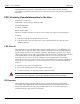
Table Of Contents
- 14-0364 - Exhibit Cover.pdf
- GPR2 Installation Guide 98-1135.pdf
- Chapter 1: Pre-Installation 7
- Chapter 2: Index Cover Pulser Install and Operation Start Up 25
- Chapter 3: American GPR Index Cover & GPR Install 31
- Chapter 4: Rockwell GPR Index Cover & GPR Install 47
- Chapter 5: Schlumberger GPR Index Cover & GPR Install 57
- Chapter 6: Sprague GPR Index Cover & GPR Install 69
- Chapter 7: Electronic Pulser Installation 85
- Chapter 8: Dresser Roots Installation 99
- Appendix A: GPR Waterproofing 113
- Appendix B: Installation in Hazardous Locations 121
- Table 1-1. Typical Gas Meter Module Installation Tool List
- Table 1-2. American Meter Index Cover Mini Switch Kits
- Table 1-3. American Large Diaphragm Meter Dial Wheels
- Table 1-4. American GPR + Brackets Kits
- Table 1-5. Kit, GPR Installation, American Large Diaphragm, Alternative Orientation #45-1189
- Table 1-6. Kit, GPR Installation, American Large Diaphragm, Behind Index #45-1190
- Table 1-7. Kit, American Large Diaphragm Alternative Orientation GPR, #45-1193
- Table 1-8. Hardware Kit, American Large Diaphragm #45-1203
- Table 1-9. GPR Assembly w/ Universal Bracket #45-1185
- Table 1-10. GPR Cover Mounting Kit #45-1042
- Table 1-11. Rockwell Large Diaphragm Meter GPR Index Cover Kit
- Table 1-12. Rockwell Large Diaphragm Meter GPR Dial Wheel
- Table 1-13. GPR Installation Kit for Rockwell 750 Large Diaphragm Meter #45-1186
- Table 1-14. Kit, Rockwell Large Diaphragm Index Cover Hardware #45-1169
- Table 1-15. GPR Assembly w/ Universal Bracket #45-1185
- Table 1-16. Schlumberger Large Diaphragm Meter GPR Index Cover Kit
- Table 1-17. Schlumberger Large Diaphragm Meter GPR Back Mount Wheel
- Table 1-18. Schlumberger Large Diaphragm GPR Kit #45-1187
- Table 1-19. Kit, Schlumberger Large Diaphragm Index Cover Hardware # 45-1171
- Table 1-20. GPR Assembly w/ Universal Bracket #45-1185
- Table 1-21. Sprague Large Diaphragm Meter GPR Kit
- Table 1-22. GPR Dial Wheels
- Table 1-23. GPR Installation Kit for Sprague Large Diaphragm Meters #45-1188
- Table 1-24. Sprague Large Diaphragm Index Cover Hardware Kit #45-1114
- Table 1-25. GPR Assembly w/ Universal Bracket #45-1185
- Table 1-26. Rotary Gas Meter Module Installation Tool List
- Table 1-27. GPR Rotary Meter Cables
- Table 1-28. GPR Installation Components for Rotary Gas Meters
- Table 1-29. GE AMR Adapter Kit
- Table 1-30. Gridstream American Residential Module
- Table 1-31. Index with Consumption Pointers Removed
- Table 2 - 1. Single Form-C Volume Wiring Definitions
- Table 7 - 1. Definitions
- Table 7 - 2. Single Form-A Volume Input Definitions
- Table 7 - 3. Two Form-A Volume Inputs Wiring Definitions
- Table 7 - 4. Two Form-A and Alarm Wiring Definitions
- Table 8 - 1. 01-1337 Index Parameters
- Table 8 - 2. M120-1 Dial Wheel and Seals Hardware Kit #45-1219
- Table 8 - 3. American Index, Pointers Removed, GE AMR (Kit #45-2400)
- Table 8 - 4. LED Startup Patterns
- Table B - 1.

Landis+Gyr Chapter 1 - Pre-Installation
Installation Guide 98-1135 Rev AB 9
Industry Canada
This device complies with Industry Canada license-exempt RSS standard(s). Operation is subject to
the following two conditions: (1) this device may not cause interference, and (2) this device must
accept any interference, including interference that may cause undesired operation of the device.
Le présent appareil est conforme aux CNR d'Industrie Canada applicables aux appareils
radiovexempts de licence. L'exploitation est autorisée aux deux conditions suivantes: (1) l'appareil
ne doitvpas produire de brouillage, et (2) l'utilisateur de l'appareil doit accepter tout brouillage
radioélectrique subi, même si le brouillage est susceptible d'en compromettre le fonctionnement.
Under Industry Canada regulations, this radio transmitter may only operate using an antenna of a
type and maximum (or lesser) gain approved for the transmitter by Industry Canada. To reduce
potential radio interference to other users, the antenna type and its gain should be so chosen that the
equivalent isotropically radiated power (e.i.r.p.) is not more than that necessary for successful
communication.
Conformément à la réglementation d'Industrie Canada, le présent émetteur radio peut fonctionner
avec une antenne d'un type et d'un gain maximal (ou inférieur) approuvé pour l'émetteur par
Industrie Canada. Dans le but de réduire les risques de brouillage radioélectrique à l'intention des
autres utilisateurs, il faut choisir le type d'antenne et son gain de sorte que la puissance isotrope
rayonnée équivalente (p.i.r.e.) ne dépasse pas l'intensité nécessaire à l'établissement d'une
communication satisfaisante.
Compliance
This apparatus is suitable for Class I, Division 1, Group D Hazardous Locations.
U WARNING: Substitution of components may impair the suitability for Class I, Division 1
applications. Replace battery only with Landis+Gyr part number 40-1235.
Substitution of components may impair intrinsic safety. Please refer to the notes in Appendix B and
to"Control Drawing 86-1006" on page -123 for connecting to this intrinsically safe device.
Preliminary Checks
1. The installer will verify correct site, as specified on work order.
2. The installer will verify that the site is safe for installer activity and equipment.
3. The installer will notify the customer of installer presence and activity, telling the customer that
meter access is required. If necessary, the installer will have the customer sign the work order.
4. When installing meters, the installer will follow guidelines issued by the utility in addition to
those given in this guide.
5. The installer will never perform an installation during a lightning storm or under excessively wet
conditions.
Site Requirements
The site must comply with the following criteria:
1. There is no chance that another object will be set over the antenna.