
User Manual

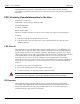
Table Of Contents
- 14-0364 - Exhibit Cover.pdf
- GPR2 Installation Guide 98-1135.pdf
- Chapter 1: Pre-Installation 7
- Chapter 2: Index Cover Pulser Install and Operation Start Up 25
- Chapter 3: American GPR Index Cover & GPR Install 31
- Chapter 4: Rockwell GPR Index Cover & GPR Install 47
- Chapter 5: Schlumberger GPR Index Cover & GPR Install 57
- Chapter 6: Sprague GPR Index Cover & GPR Install 69
- Chapter 7: Electronic Pulser Installation 85
- Chapter 8: Dresser Roots Installation 99
- Appendix A: GPR Waterproofing 113
- Appendix B: Installation in Hazardous Locations 121
- Table 1-1. Typical Gas Meter Module Installation Tool List
- Table 1-2. American Meter Index Cover Mini Switch Kits
- Table 1-3. American Large Diaphragm Meter Dial Wheels
- Table 1-4. American GPR + Brackets Kits
- Table 1-5. Kit, GPR Installation, American Large Diaphragm, Alternative Orientation #45-1189
- Table 1-6. Kit, GPR Installation, American Large Diaphragm, Behind Index #45-1190
- Table 1-7. Kit, American Large Diaphragm Alternative Orientation GPR, #45-1193
- Table 1-8. Hardware Kit, American Large Diaphragm #45-1203
- Table 1-9. GPR Assembly w/ Universal Bracket #45-1185
- Table 1-10. GPR Cover Mounting Kit #45-1042
- Table 1-11. Rockwell Large Diaphragm Meter GPR Index Cover Kit
- Table 1-12. Rockwell Large Diaphragm Meter GPR Dial Wheel
- Table 1-13. GPR Installation Kit for Rockwell 750 Large Diaphragm Meter #45-1186
- Table 1-14. Kit, Rockwell Large Diaphragm Index Cover Hardware #45-1169
- Table 1-15. GPR Assembly w/ Universal Bracket #45-1185
- Table 1-16. Schlumberger Large Diaphragm Meter GPR Index Cover Kit
- Table 1-17. Schlumberger Large Diaphragm Meter GPR Back Mount Wheel
- Table 1-18. Schlumberger Large Diaphragm GPR Kit #45-1187
- Table 1-19. Kit, Schlumberger Large Diaphragm Index Cover Hardware # 45-1171
- Table 1-20. GPR Assembly w/ Universal Bracket #45-1185
- Table 1-21. Sprague Large Diaphragm Meter GPR Kit
- Table 1-22. GPR Dial Wheels
- Table 1-23. GPR Installation Kit for Sprague Large Diaphragm Meters #45-1188
- Table 1-24. Sprague Large Diaphragm Index Cover Hardware Kit #45-1114
- Table 1-25. GPR Assembly w/ Universal Bracket #45-1185
- Table 1-26. Rotary Gas Meter Module Installation Tool List
- Table 1-27. GPR Rotary Meter Cables
- Table 1-28. GPR Installation Components for Rotary Gas Meters
- Table 1-29. GE AMR Adapter Kit
- Table 1-30. Gridstream American Residential Module
- Table 1-31. Index with Consumption Pointers Removed
- Table 2 - 1. Single Form-C Volume Wiring Definitions
- Table 7 - 1. Definitions
- Table 7 - 2. Single Form-A Volume Input Definitions
- Table 7 - 3. Two Form-A Volume Inputs Wiring Definitions
- Table 7 - 4. Two Form-A and Alarm Wiring Definitions
- Table 8 - 1. 01-1337 Index Parameters
- Table 8 - 2. M120-1 Dial Wheel and Seals Hardware Kit #45-1219
- Table 8 - 3. American Index, Pointers Removed, GE AMR (Kit #45-2400)
- Table 8 - 4. LED Startup Patterns
- Table B - 1.

1
Installation Guide 98-1135 Rev AB 7
Pre-Installation
Before You Begin
This text contains the symbols which are explained below.
NOTE: Notes provide important information about products and installation.
A CAUTION: Cautions provide information that you must read to avoid making relatively
moderate errors.
U WARNING: Warnings provide special, must-read information. If you ignore a warning you may
create a safety hazard, omit essential data, or make a critical error.
Safety Overview
NOTE: Proper planning and thorough preparation are critical for successful installation. This
chapter outlines basic requirements for the pre-installation phase.
Prior to starting the installation process, you must develop and launch an installer safety training
plan for initial, refresher, and ongoing safety training. Ensure that installers receive appropriate
initial and refresher training to meet their specific safety-related responsibilities. Installers should be
instructed in the following safety elements as well as any site-specific safety issues.
• New duties for which the installer has not previously received training.
• New processes and methodologies representing new risks that are introduced into
the
inst
allation environment.
• Situations where previously unidentified risks are reported.
• Hazard Communication (Employee Right to Know)
• Lifting
• Safe driving
• Use of hand tools
• Confined space
The installation supervisory team assumes responsibility for ensuring that installers are properly
trained, authorized, and continually qualified to perform their work. The team must also take
responsibility for the safety of their installers and to assure safe work methodologies. Installers must