Certification Exhibit FCC ID: R7PGRAMCNLX1 IC: 5294A-GRAMCNLX1 FCC Rule Part: 15.247 IC Radio Standards Specification: RSS-210 ACS Report Number: 08-0433 - 15C Manufacturer: Cellnet Technology, Inc. Model: GasLX Residential American Installation Guide 5015 B.U.
American Residential Meter One-Way Gas Module Installation Guide 98-3107 Rev AA
Limitation on Warranties and Liability Information in this document is subject to change without notice. This manual or any part of it thereof may not be reproduced in any form unless permitted by contract or by written permission of Landis+Gyr.
Table of Contents Chapter 1: Preface Chapter 2: Pre-Installation . . . . . . . . . . . . . . . . . . . . . . . . . . . . . . . . . . . . . . . . . . . . . . . . . . . . . . . . . . . 7 Chapter 3: Using the HandHeld Device . . . . . . . . . . . . . . . . . . . . . . . . . . . . . . . . . . . . . . . . . . . . . . . . . 15 Chapter 4: On-Site Preparation . . . . . . . . . . . . . . . . . . . . . . . . . . . . . . . . . . . . . . . . . . . . . . . . . . . . . . . 37 Chapter 5: Gas Meter Exchange . . . . . . .
Table of Contents ii Landis+Gyr 98-3107 Rev AA One-way Gas Module Installation Guide
1 Preface This guide describes the installation process for Landis+Gyr American Residential Meter One-Way Gas Module. Any training provided directly to installers by the utility or by the Landis+Gyr project management team takes precedence over this guide, as long as it does not involve altering the meter module retrofit process. About This Guide This is the November 2008 edition of the Landis+Gyr American Residential Meter One-Way Gas Module Installation Guide.
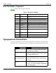
Chapter 1 - Preface Landis+Gyr How This Guide Is Organized Table 1-2 illustrates how this guide is organized. Table 1-1.
Landis+Gyr Chapter 1 - Preface Convention Description Plus sign (+) between keys Refers to pressing the keys at the same time. Example: Alt+B. Comma (,) between keys Refers to keys which are pressed sequentially. Example: Alt,F. Note boxes provide essential information about Landis+Gyr Gas Meter Module and Meter Installation. Cautions provide information that you must read to avoid making relatively moderate errors during Landis+Gyr Gas Meter Module and Meter Installation.
Chapter 1 - Preface Landis+Gyr Email Access If you prefer, you may email a description of your problem to: solutionsupport.na@landisgyr.com A support technician will return your email as soon as possible within normal business hours. Technicians return all emails in the order that they are received. General Inquiries Your feedback is important in helping to provide the most accurate and high-quality information.
Landis+Gyr Chapter 1 - Preface Related Publications The following document provides important related information. Table 1-2.
Preface Notes: 6 One-way Gas Module Installation Guide
2 Pre-Installation Proper planning and thorough preparation are critical for successful installation. This chapter outlines basic requirements for the pre-installation phase. SAFETY OVERVIEW Prior to starting the installation process, you must develop and launch an installer safety training plan for initial, refresher, and ongoing safety training. Ensure that installers receive appropriate initial and refresher training to meet their specific safety-related responsibilities.
Chapter 2 - Pre-Installation Landis+Gyr Table 2-1. Gas Meter Installation and Module Retrofit Tool List píêÉÉí=^íä~ë oc=_ìëíÉêI=mLk=OSJNMRM kçåJëé~êâ=Ñä~ëÜäáÖÜí `Éää=éÜçåÉ=çê=OJï~ó=ÅçããìåáÅ~íáçå= ÇÉîáÅÉ táêÉ=_êìëÜ `~ÄäÉ=íáÉë “pÜççíÉêÒ=Å~ÄäÉ gìãéÉê=Å~ÄäÉë iÉ~â=ÇÉíÉÅíáçå=ëç~é mêÉëëìêÉ=Ö~ìÖÉë dêÉó=ëéê~ó=é~áåí=~åÇ=é~áåí=Äç~êÇ=Eíç= éêÉîÉåí=çîÉê=ëéê~óáåÖF aÉ~Ç=Ääçï=Ü~ããÉê ^åó=êÉèìáêÉÇ=ëéÉÅá~äíó=íççäë Your supervisor carries shovels, spades, hack saws, other specialty tools, and ladders.
Landis+Gyr Chapter 2 - Pre-Installation Handhelds (Handheld) Handhelds are rugged, but you should still always handle them carefully. If the unit fails to operate in the field, page your Supervisor for help. If possible, the Supervisor will assist in correcting the problem or bring a replacement unit out to you. Figure 2 - 2. Handhelds with programming cables Handhelds differ by program, but the ones shown above are currently in service. On the left is the DAP PC9800, a DOS-based Handheld.
Chapter 2 - Pre-Installation Landis+Gyr Meter Compatibility This Gas meter Compatibility List is the result of retrofit experience and feedback from American Meter. Every attempt has been made to ensure the accuracy of the information in this table. There may be limitations to compatibility unknown to Landis+Gyr due to changes made which L+G has been unable to document through our research and substantial meter library.
Landis+Gyr Chapter 2 - Pre-Installation Compliance This apparatus is suitable for Class I, Division 1, Group D Hazardous Locations. Warning - Explosion Hazard - Substitution of components may impair suitability for Class I, Division 1.
Chapter 2 - Pre-Installation Landis+Gyr FCC & Industry Canada Information to the User Manufacturer: Cellnet Model Name: GasLX FCC ID: R7PGRAMCNLX1 IC: 5294A-GRAMCNLX1 This device complies with Part 15 of the FCC rules. Operation is subject to the following two conditions: 1 This device may not cause harmful interference, and 2 This device must accept any interference received, including interference that may cause undesired operation.
Landis+Gyr One-way Gas Module Installation Guide Chapter 2 - Pre-Installation 98-3107 Rev AA 13
Pre-Installation Notes: 14 One-way Gas Module Installation Guide
3 Using the HandHeld Device The DAP 5320b is a portable and rechargeable HandHeld computer unit. Its electric components are protected in hard plastic housing. The features of the DAP 5320B include • Windows-CE-based color LCD display • Alphanumeric keypad • Integrated barcode scanner • 7-pin LEMO is used for charging the HandHeld or uploading/downloading from RIMS • Automatic shutoff to maximize battery life • Hand strap for secure handling.
Chapter 3 - Using the HandHeld Device Landis+Gyr Display The DAP Handheld uses a TFT liquid crystal display (LCD). Figure 3 - 2. CE Display High-contrast characters are easily visible in normal light. Instructions for each screen display at the top of each screen in blinking red letters. The Handheld displays a tabbed view where you advance one screen at a time. You can go back as many screens as you want.
Landis+Gyr Chapter 3 - Using the HandHeld Device Keyboard The keys on the keyboard are labeled with primary functions (such as: I/O (PWR), ESC, SP, BKSP), the 26-character alphabet, 0-9 numbers, and various symbols. Enter data by pressing the appropriate key. Enter other functions by pressing the FUNC (blue) key first, then pressing the corresponding alphanumeric keys. Figure 3 - 3.
Chapter 3 - Using the HandHeld Device Landis+Gyr Program Conventions • Keys are active for the displayed function. For example, if text is required, the alphanumeric keys are active; if a display option is to be selected, the Arrow Cursor Pad may be used as a tab key. If there is a list or drop-down type menu, there will be small arrows on the screen indicating that the Arrow Cursor Pad should be used for the selection.
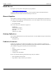
Landis+Gyr Chapter 3 - Using the HandHeld Device Standard Meter Installation and/or Module Retrofit This section covers the installer steps and Handheld screens for the meter exchange process or gas module retrofit. Check Route Status 1 Start the Handheld PC by pressing the I/O / F1 power key . The screen below displays. If this screen does not display, press Enter or ESC keys to get to the Customer Address screen. Figure 3 - 4.
Chapter 3 - Using the HandHeld Device Landis+Gyr The Handheld PC can be shut off during installation with the automatic shutoff feature or by pressing the FUNC and then the I/O / F1 power key The unit retains existing data and remains at the last step performed until it is turned on again and additional data is entered. 4 Press Enter to display first address for displayed route. Check Address The address screen shows the account’s address and any other information pertinent to the installation process.
Landis+Gyr Chapter 3 - Using the HandHeld Device Table 3-2. Handheld Options and Active Keys for Route Status screen Option or Active Key Function bp` oÉíìêåë=íç=íÜÉ=mêÉîáçìë=ëÅêÉÉå båíÉê p~îÉë=ÅÜ~åÖÉë=~åÇ=~Çî~åÅÉë=íç=íÜÉ=åÉñí=ëÅêÉÉå If the address or instructions exceed the length of the window, vertical scroll bars display. Arrow Cursor Pad moves the display up or down. 1 Press ENTER to view instructions. Figure 3 - 6.
Chapter 3 - Using the HandHeld Device Landis+Gyr Utility Field Data Collection Figure 3 - 7. Handheld Utility Field Data screen This screen varies—or is not used—depending on the utility. In this example, the utility company requires a description of meter location. 1 Select the relevant option and press the Enter key. Meter Information After pressing Enter, the Handheld PC displays the following prompts for drive constant and meter reading. Figure 3 - 8.
Landis+Gyr Chapter 3 - Using the HandHeld Device Table 3-4. Handheld Options and Active Keys for Meter Reading Option or Active Key 1 Function båíÉê p~îÉë=~åó=ÅÜ~åÖÉë=~åÇ=~Çî~åÅÉë=íç=íÜÉ=åÉñí=ëÅêÉÉåK bp` oÉíìêåë=íç=íÜÉ=êçìíÉ=ëí~íìë=ëÅêÉÉå Select the appropriate drive constant. Installer must verify that the drive constant is equivalent to the dial cubic foot as indicated below. Dial Figure 3 - 9. Generic Meter Dial Configuration Table 3-5.
Chapter 3 - Using the HandHeld Device • Landis+Gyr The first dial counted is the 1,000 CF/rotation. Count up to the highest dial. START HERE Figure 3 - 11. Handheld Start counting dials Table 3-6.
Landis+Gyr Chapter 3 - Using the HandHeld Device • Allowable percentage variation (utility specific). If this check is not in place you will be prompted to enter the last four numbers of the meter ID and to re-enter the read. . Table 3-7. Handheld Options and Active Keys for Meter Reading Option or Active Key MJV Function båíÉêë=êÉ~ÇK båíÉê p~îÉë=~åó=ÅÜ~åÖÉë=~åÇ=~Çî~åÅÉë=íç=íÜÉ=åÉñí=ëÅêÉÉåK bp` oÉíìêåë=íç=íÜÉ=êçìíÉ=ëí~íìë=ëÅêÉÉå 1 Enter reading for existing meter in meter read screen.
Chapter 3 - Using the HandHeld Device Landis+Gyr 1 Connect the Handheld PC to the meter module (refer to appropriate installation procedure). 2 Check to ensure that the information that you entered into the Handheld is correct, such as drive constant, Index read, and meter ID. For example, dials=4, meter ID=0123456G, meter constant=2. 3 Press ENTER to begin programming the meter module.
Landis+Gyr Chapter 3 - Using the HandHeld Device Figure 3 - 16. Handheld redisplays information Meter information redisplays to verify the meter read and meter ID. . Table 3-9.
Chapter 3 - Using the HandHeld Device 2 Landis+Gyr Perform technical review of meter. Enter the appropriate code in your Handheld, and then call your Supervisor for support. Figure 3 - 17. Handheld Read out of Range screen The software requests the last four numbers of existing meter ID to confirm that the meter belongs to this account. If meter ID does not match, the account address is redisplayed for verification or depending on utility, specific instructions display. . Table 3-10.
Landis+Gyr Chapter 3 - Using the HandHeld Device . Table 3-11. Handheld Options and Active Keys for Read Out of Range Option or Active Key 4 Function MJV båíÉêë=íÜÉ=ãÉíÉê=fa båíÉê p~îÉë=~åó=ÅÜ~åÖÉë=~åÇ=~Çî~åÅÉë=íç=íÜÉ=åÉñí=ëÅêÉÉå bp` oÉíìêåë=íç=ãÉíÉê=êÉ~Ç=ëÅêÉÉå Re‐enter meter reading. Meter ID Confirmation This section covers possible screens generated for invalid meter ID entries. Figure 3 - 19. Meter already used The changeout meter ID entered was used on another address. Table 3-12.
Chapter 3 - Using the HandHeld Device Landis+Gyr This function updates the HandHeld — even though the existing meter will be replaced with the new change-out meter. Figure 3 - 20. Handheld Meter ID Change screen Skips In some situations, you cannot install a gas module or replace the existing meter. You must skip it; for example, the meter is located in the house or an enclosed area and requires you to make arrangements with the customer for access. Figure 3 - 21.
Landis+Gyr Chapter 3 - Using the HandHeld Device Figure 3 - 22. Handheld Skip screen Choices on the Skip screen include: • No access • Key needed • Locking ring • Unsafe condition exists • Medical • Dog • Appointment needed • No Meter • Meter Damaged • Red/Yellow Tag • Diversion • Violence code • Buried meter • Tilted meter • Found meter • Disconnected or Shutoff meter • Obstacle/Blocked Table 3-1.
Chapter 3 - Using the HandHeld Device Landis+Gyr 4 Select reason for skipping meter and press ENTER. 5 Select Ok to accept reason for skipping meter ID. If you want to add a comment, select the Comment option. The software displays the selected skip cause and requests confirmation to skip meter installation. Figure 3 - 23. Handheld Skip Confirmation screen Table 3-14.
Landis+Gyr Chapter 3 - Using the HandHeld Device Problems You can indicate up to four problems to record in a route’s record. Figure 3 - 24. Problem Indication screen Table 3-15.
Chapter 3 - Using the HandHeld Device • Address • Customer Name • LAN Address Landis+Gyr Route Status Options include: • Exchanged • All • ToDo • Completed • Skipped Table 3-16.
Landis+Gyr Chapter 3 - Using the HandHeld Device • Arrow keys move the cursor from the Find field to the data records. • Space (SP) key moves from addresses to Find field. Table 3-17.
Using the HandHeld Device Notes: 36 One-way Gas Module Installation Guide
4 On-Site Preparation Arrival at Install Site 1 Upon arriving at the installation site, verify the address in the Handheld. Check the Handheld for special instructions for that site (for example, medical customer, dog, key required for access to meter, meter location, and so on). If a medical alert code appears in the Handheld for that address they are to skip the install enter an appropriate skip code and move to the next exchange. A medical alert tag may be located on the electric meter.
On-Site Preparation Notes: 38 One-way Gas Module Installation Guide
5 Gas Meter Exchange Meter Exchange Process Arriving at the Location 1 The installer confirms that they are at the right route address for that appointment using the Handheld. The installer arrives at the location on‐time and with all the tools and equipment necessary to complete the installation without having to return to the support vehicle. If applicable, locate the outside shutoff valve in case of trouble or emergency.
Chapter 5 - Gas Meter Exchange Landis+Gyr Confirming Proper Installation Conditions 1 2 For the installation to qualify, confirm ALL of the following pre‐existing conditions: – Visually examine the shut‐off that it does NOT show signs of leaking or disrepair. – Perform the sniff test for signs of gas leaks using the Natural Gas Detection Device, and then the soap test on the shut off and couplings.
Landis+Gyr Chapter 5 - Gas Meter Exchange Installing the New Meter 1 Remove the new meter tag from the new meter. 2 Write install date, address, and initials on new meter tag. 3 Place new meter tag on the old meter register. 4 Insert new gaskets where applicable. 5 Exchange the regulator if damaged or outdated, and exchange any damage insulating unions. Level the meter set if the set is tilted. 6 Tighten the inlet‐coupling nut.
Chapter 5 - Gas Meter Exchange Landis+Gyr Programming the Module Refer to Chapter 3, Using the HandHeld Device. Performing Data Collection 1 See Chapter 3, Using the HandHeld Device. 2 Seal the new meter. Cleaning Up the Work Area Clean up all installation tools, equipment and debris. Turn off any lights that you may have turned on. Restore the customer premise to the pre-visit condition. Exiting the Premise 1 Do a last check to ensure that you have all of your equipment and tools.
Landis+Gyr Chapter 5 - Gas Meter Exchange Battery Change Out When the NOC analyst notices that the battery flag (R) is set, it could be due to: • a single end-point occurrence, where the end-point may require more current to operate.
Gas Meter Exchange Notes: 44 One-way Gas Module Installation Guide
6 Meter Module Retrofit This chapter outlines the procedure for Meter Module installation. There are many meter module types supported. Two examples appear below. Figure 6 - 1.
Figure 6 - 2. Meter Module kit before installation 4 Follow steps 1‐4 in ʺTo Begin Meter Module Retrofitʺ on page ‐45. Figure 6 - 3. Index and Gas LX Index Cover 5 Remove all of the original gasket material. Replace the index if it is damaged or if the gears are discolored. Metal indexes cannot be used and must be replaced.
Landis+Gyr Chapter 5 - Meter Module Retrofit WHEN REPLACING AN INDEX, YOU MUST ENTER THE METER READ INTO THE HANDHELD AND NOTE “INDEX EXCHANGED” IN THE COMMENT SECTION. For Index visual verification and exchange, see Appendix A, Supplemental Information About Indexes. Figure 6 - 4. Removing the Index (one screw on each side) 6 Clean the area behind the index and cover gasket surface on the meter with a wire brush and gasket scraper.
Figure 6 - 6. Installing the battery with the battery cable on top Figure 6 - 7. Properly installed battery Figure 6 - 8.
Landis+Gyr Chapter 5 - Meter Module Retrofit After the battery is installed, prepare to install the Dial Wheel . Figure 6 - 9. Dial Wheel Kit 10 Clip the pieces apart. Figure 6 - 10. Dial Wheel Kit separated for installation Figure 6 - 11. Reader Interface Dial Wheel Needle Slot 11 While holding the Dial Wheel (DW), note the location of the Needle Slot. With the index sitting on a work surface, set the DW on the index face with the needle slot oriented towards the needle.
Chapter 5 - Meter Module Retrofit Landis+Gyr Figure 6 - 12. Dial Wheel with needle slot positioned for unit needle entrance 12 Slide the DW toward the needle... Figure 6 - 13. Moving the Dial Wheel onto the index unit pointer ...until the DW center contacts the needle mount. The needle mount center will gently impede the Dial Wheel. Figure 6 - 14.
Landis+Gyr Chapter 5 - Meter Module Retrofit 13 Take the DW Pin and insert the pin into the DW hole. You will feel a gentle snap as the pin seats into place. Figure 6 - 15. Installing the Dial Wheel Pin 14 Prepare to mount the Dial Wheel on the meter by locating the meter Wiggler and starting a bare minimum of the threads for one of the Meter Index mounting screws. The following picture shows the screw to the left of the wiggler installed. Figure 6 - 16.
Chapter 5 - Meter Module Retrofit Landis+Gyr All photographs and installation steps in this procedure refer to “2-foot” meters. For a “1-foot” meter installation, the Meter Wiggler and the Meter Index Drive Pin are of a slightly different configuration, as shown in the following photograph. All installation steps are identical except for the meter and drive pin configuration. Figure 6 - 18.
Landis+Gyr Chapter 5 - Meter Module Retrofit 17 After aligning the Meter Index Drive Pin with the Meter Wiggler, move the Meter Index into operating position, hold the Meter Index with one hand and tighten the mounting screw enough turns to hold the Meter Index in place as you prepare to install the other Meter Index mounting screw. Figure 6 - 20.
Chapter 5 - Meter Module Retrofit Landis+Gyr Figure 6 - 22. Installing the next Meter Index Cover mounting screw 19 Install the remaining screws. Tighten the screws until the cover sits snug, then tighten the screws an additional quarter turn. Prepare to verify that the module is transmitting. Figure 6 - 23.
Landis+Gyr Chapter 5 - Meter Module Retrofit Figure 6 - 24. Meter module with tamper seals installed 22 Clean up debris from the retrofit and installation processes. Enter the appropriate infomation on a door hanger tag. A door hanger tag must always be left after a meter is exchanged. 23 At the end of the day, the installer returns to the Cross Dock for the check‐in process. The installer should also turn in inventory of unused, defective, or broken gas Meter Modules.
Chapter 5 - Meter Module Retrofit 56 Landis+Gyr 98-3107 Rev AA One-way Gas Module Installation Guide
7 Gas Meter Preparation Program (GPrep) The Gas Meter Preparation Program (GPrep) is a software tool that facilitates Landis+Gyr processes. It also runs with water CPR modules. The data captured by GPrep is sent to RIMS to update the Landis+Gyr and utilities databases.
Chapter 7 - Gas Meter Preparation Program (GPrep) Landis+Gyr Required Tools The following is a list of required tools to operate GPrep, along with a PC / operating system recommendation: • Desktop PC with Windows 2000 or higher (Windows NT is not recommended when using a laptop computer since there are sometimes problems configuring the ports) • Copy of GPrep v. 2.
Landis+Gyr Chapter 7 - Gas Meter Preparation Program (GPrep) c Follow the instructions in that file to specify the required pattern for Meter IDs, file(s) for logging operations, menu selections that are available to the operator and the maximum memory used to track previous log file associations. If you run GPrep in different modes and/or it requires different configuration settings at the same operator station, then install multiple copies of GPrep in different directories.
Chapter 7 - Gas Meter Preparation Program (GPrep) ; ; ; ; ; ; ; ; ; ; ; ; ; ; ; ; ; ; ; ; ; ; ; ; ; ; ; ; ; ; ; ; ; ; ; ; ; ; ; ; ; ; ; ; ; ; ; ; ; ; ; ; ; ; ; ; ; ; ; ; ; 60 Landis+Gyr COM1=Yes Disables "COM3" and "COM4" selections, leaving "COM1" and "COM2" enabled. -----------------------------------------------------------------------------MeterID is a pattern string for scanned (or entered) Meter IDs.
Landis+Gyr Chapter 7 - Gas Meter Preparation Program (GPrep) ; ReadLog=readdlog - readdlog.txt in the GPrep program directory ; ReadLog=- Do not write an inspection log file ; -----------------------------------------------------------------------------; MaxAssociations is the maximum number of LANAddress / Meter ID associations ; checked from the log file to assure that duplications are not assigned. ; This requires 24 bytes of memory per association. Set to 0 to disable.
Chapter 7 - Gas Meter Preparation Program (GPrep) Landis+Gyr MeterConstant1=.01 MeterConstant2=.0112 MeterConstant3=.02 MeterConstant4=.0225 RollOverPointCount=5 RollOverPoint1=100 RollOverPoint2=1,000 RollOverPoint3=10,000 RollOverPoint4=100,000 RollOverPoint5=100000000 [CPRAWT] MeterConstantCount=9 MeterConstant1=.01 MeterConstant2=.01121 MeterConstant3=.02 MeterConstant4=.0225 MeterConstant5=.05 MeterConstant6=.0562 MeterConstant7=.1 MeterConstant8=.112 MeterConstant9=1.
Landis+Gyr Chapter 7 - Gas Meter Preparation Program (GPrep) RollOverPoint1=100 RollOverPoint2=1,000 RollOverPoint3=10,000 RollOverPoint4=100,000 RollOverPoint5=99999999 [CIGR] MeterConstantCount=5 MeterConstant1=.05 MeterConstant2=.0562 MeterConstant3=.1 MeterConstant4=.112 MeterConstant5=1.0 RollOverPointCount=5 RollOverPoint1=100 RollOverPoint2=1,000 RollOverPoint3=10,000 RollOverPoint4=100,000 RollOverPoint5=100,0000 [CIGD] MeterConstantCount=5 MeterConstant1=.05 MeterConstant2=.0562 MeterConstant3=.
Chapter 7 - Gas Meter Preparation Program (GPrep) Landis+Gyr Utility shop location can post multiple files, as long as each file is uniquely identified. The local site can use any logic to name these files, preferably to include date and time. Once these files are posted, the DES server validates file format and cleanup activities by eliminating duplicate entries and storing the program logs and MRB data in staging tables. The server emails subscribers from source location.
Landis+Gyr Chapter 7 - Gas Meter Preparation Program (GPrep) . Figure 7 - 2. Shooter box with data cable Logging On The Log On window displays when you launch the program. Enter your name and location in the appropriate fields. All tasks you perform for a given meter type (module inspection, new module programming, old module reprogramming, MRB and index read) will be recorded. Figure 7 - 3. Log On screen Accessing the Main Menu The main menu screen displays after you log on. Figure 7 - 4.
Chapter 7 - Gas Meter Preparation Program (GPrep) Landis+Gyr Program Type: Select Interval or Consumption type data. Mode: provides the following choices: • Inspect: Verifies that the programmed LAN Address has the same value as the Power LAN Address label. In addition, “Inspect” permits validating the other pre-configured operational parameters. Discrepancies are noted through message windows and the results of inspections are captured in associated files.
Landis+Gyr Chapter 7 - Gas Meter Preparation Program (GPrep) The following screens show how the operator has the option of choosing inspect, program new, and index read when Gas LX is chosen as the Meter Type. Figure 7 - 5. Choose Gas LX as the meter type Figure 7 - 6. Indicate the Program Type Figure 7 - 7. Modes to choose from are “Inspect” or “Program New” • Control: provides the capability to log on and off. The program setting remains the same when a new operator logs on.
Chapter 7 - Gas Meter Preparation Program (GPrep) Landis+Gyr Module Inspection This feature is most commonly used when receiving meters from the factory with Landis+Gyr modules already installed (OEM Meters) or when receiving Landis+Gyr modules from Landis+Gyr’s manufacturer. Different utilities use different sampling procedures.
Landis+Gyr Chapter 7 - Gas Meter Preparation Program (GPrep) The lower section, “current parameters”, displays the operational parameters and module programmed values. 2 Connect the shooter cable to the module programming port. The following screen displays. Figure 7 - 9. “Inspect Mode” Screen With Module Plugged In GPrep automatically reads and displays the current parameters programmed into the module.
Chapter 7 - Gas Meter Preparation Program (GPrep) 3 Landis+Gyr Scan (enter) the Module ID in LAN Address field. Figure 7 - 10. “Inspect Mode” With Power LAN Scanned In GPrep compares the Module ID entered in this field with the LAN Address programmed into the module. If the populated field matches the programmed value, a message displays “address verified”.
Landis+Gyr Chapter 7 - Gas Meter Preparation Program (GPrep) There are two distinct sections in this screen as well. The top section contains the following fields which can be modified by the user: • Meter ID field If you are programming a Water CPR module, Device ID replaces Meter ID. A CPR module is programmed with 10-digit left-justified (zero) Module ID as MeterID. Water CPR programming also captures optional Encoder ID information. • LAN Address • Roll-over point • Meter constant.
Chapter 7 - Gas Meter Preparation Program (GPrep) 2 Landis+Gyr Connect the 1‐Way Programming Cable or shooter cable to the module programming port. The following screen displays. Figure 7 - 12. “Program New” Screen with Module Plugged In GPrep automatically reads and displays the current parameters programmed into the module.
Landis+Gyr Chapter 7 - Gas Meter Preparation Program (GPrep) 4 Scan (enter) the power LAN label in the LAN Address field. “GPrep” compares the value entered in this field with the LAN Address programmed in the module. Similar to the inspection section, any discrepancies in the values are rejected. Figure 7 - 14.
Chapter 7 - Gas Meter Preparation Program (GPrep) Landis+Gyr A record of the meter and module association is automatically captured in the “program file” including the date and the operator’s name. The “Programlog” only compiles the records when successful programming is verified. If a Meter ID record already exists in programlog, the following message displays. Figure 7 - 16.
Landis+Gyr Chapter 7 - Gas Meter Preparation Program (GPrep) Re-Program Old The instructions and procedures for Re-Program Old are the same as those for Program New, with the additional field “Dial”. Populate it with the index reading (dial reading). This mode is mainly utilized during the O&M phase to program meters with non-zero indices. 1 Select Re‐Program Old from the mode drop‐down window in the main menu. The following screen displays. Figure 7 - 18.
Chapter 7 - Gas Meter Preparation Program (GPrep) 2 Landis+Gyr Connect the 1‐Way Programming Cable or shooter cable to the module programming port. The following screen displays. Figure 7 - 19. Re-Program Old With Module Plugged In GPrep automatically reads and displays the current parameters programmed into the module. If the current parameters do not match the predetermined value, a warning message, “reject parameters” displays.
Landis+Gyr Chapter 7 - Gas Meter Preparation Program (GPrep) If you do not know what to enter for the Rollover Point or Meter Constant STOP! Contact someone that does know or contact Landis+Gyr Customer Support. The wrong data entered in these fields significantly affects the billing read provided to the utility. 5 Enter the index dial values by reading the dials and entering the values read from right to left.
Chapter 7 - Gas Meter Preparation Program (GPrep) 2 Landis+Gyr Select MRB from mode in the menu bar. The following screen displays. Figure 7 - 21. MRB Mode Main Menu There are two distinct sections on this screen as well. The top section contains the following fields: • LAN Address • Dial These are the only fields that can be populated. 3 Connect the 1‐Way Programming Cable or shooter cable to the module programming port. The following screen displays. Figure 7 - 22.
Landis+Gyr Chapter 7 - Gas Meter Preparation Program (GPrep) If the Meter Type selected on the menu bar does not match the module type under test, GPrep displays a dialog box indicating “wrong module Type” and a blinking “Module reject” message. GPrep does not allow the operator to resume programming function. If the current parameters do not match the predetermined value, a warning message, “reject parameters” displays. 4 Scan (enter) the Module ID in LAN Address field.
Chapter 7 - Gas Meter Preparation Program (GPrep) Landis+Gyr Frequently Asked Questions 1 What does GPrep stand for? Gas TOMM Preparation 2 What is GPrep used for? GPrep is a tool used in the Cross Dock or meter shop to program gas or water CPR modules without the use of a handheld. It is also used to disassociate gas or water CPR modules from meters. 3 What is programmed into the module? In the “Program New” and “Re‐Program Old” modes, field operating parameters are programmed into the module.
Landis+Gyr Chapter 7 - Gas Meter Preparation Program (GPrep) 12 What are some troubleshooting steps if GPrep is not working? – If you are using the shooter box, check: — AC power — module plugged in — shooter box turned on — correct DB9 to DB9 (RS‐232) cable (Non‐Null Modem) — correct COM port — correct meter type and mode (e.g. Gas LX v. commercial) – If you are using USB one way programming cable, refer to the 1‐Way Module Programming Cable PC/Laptop Getting Started Guide.
Gas Meter Preparation Program (GPrep) Notes: 82 One-way Gas Module Installation Guide
A Supplemental Information About Indexes Index Type Metal indexes cannot be used with the Gas LX system. If the meter has a metal index, the index MUST BE EXCHANGED for a plastic index. Figure A - 1. Metal American Index Figure A - 2.
Supplemental Information About Indexes Notes: 84 One-way Gas Module Installation Guide
B Using the RF Buster This Appendix provides instructions on the proper use of the RF Buster. It covers the proper placement of the RF Buster to ensure activation and troubleshooting for L+G gas modules. Required Tools RF Buster - part number 26-1050 Before using the RF Buster, test it. Press the button on the RF Buster. The RF Buster’s LED lights red, and the internal speaker sounds for approximately ½ second.
Appendix B - Using the RF Buster Landis+Gyr Residential Meter Modules 1 With the light facing you, press the button on the lower end of the RF Buster. 2 Place the corner of the RF Buster containing the magnet by the location of the reed switch on the Meter Module. 3 Continue to press the button. Hold the RF Buster within about six inches of the meter. The magnet triggers ten RF transmissions from the gas module, with each transmission separated by one second.
Landis+Gyr One-way Gas Module Installation Guide Appendix B - Using the RF Buster 98-3107 Rev AA 87
Using the RF Buster Notes: 88 One-way Gas Module Installation Guide
C End of Day Handheld Instructions This Appendix provides detailed instructions on docking the Handheld, power requirements, and how to change the Handheld ID. This information should only be used by experienced users. Docking the Handheld At the end of the day (and at other times for various reasons), dock the Handheld to upload meter installation data and plug it in to recharge the battery. 1 Select DOCK from the functions screen. Figure C-1.
Appendix C - End of Day Handheld Instructions 3 Landis+Gyr After data has been uploaded, plug Handheld into charging cable. Figure C-2. Handheld DAP charging Power Requirements Never allow the battery to die completely. Although the route data saves to the flash memory card, there is no EPROM memory in the Handheld. You will have to reload the code and re-calibrate the battery. Do not remove the battery. The batteries are not made to be replaced as with the other Handhelds.
Landis+Gyr Appendix C - End of Day Handheld Instructions How To Change The Handheld ID Occasionally the Handheld ID may be entered incorrectly or the wrong Handheld ID may be in a Handheld because of a memory card exchange. This section tells how to change the Handheld ID to the correct number. 1 Place the Handheld in the cradle and dock it. 2 Open up the most recent version of Handheld Edit. 3 Select “Communication” then “Transfer Files” from the menu on Handheld Edit.
End of Day Handheld Instructions Notes: 92 One-way Gas Module Installation Guide
GLOSSARY AMR Automated Meter Reading. Energy use data gathering from utility meters by any means other than walking up to the meter, looking at the dials, and recording the meter read for billing. C.F.H. Cubic feet per hour DES Server Data Exchange Server GPrep ʺGas Prepʺ A software program that enables the user to program, reprogram, inspect, read, and disposition to scrap an L+G gas or CPR water module.
Glossary Notes: 94 One-way Gas Module Installation Guide
Reader’s Comment Form American Residential Meter One‐Way Gas Module Installation Guide (98‐3107 Rev AA) Please use this form only to identify publication errors or to request changes in publications. Your comments assist us in improving our publications. Direct any requests for additional publications, technical questions about systems, changes in support, and so on, to your Landis+Gyr sales representative.
cçäÇ=eÉêÉ Landis + Gyr Attn.: Marketing Communications 30000 Mill Creek Ave.