Certification Exhibit FCC ID: R7PNG6R1S1 IC: 5294A-NG6R1S1 FCC Rule Part: 15.247 IC Radio Standards Specification: RSS-210 ACS Project Number: 11-0082 Manufacturer: Cellnet Technology, Inc. Model: Collector C6400, Collector C6420, Collector C6430 Manual 5015 B.U.
C6400-Series Collector Installation and User Guide Publication: 98-1095 Rev AA LANDIS+GYR CONFIDENTIAL INFORMATION
Limitation on Warranties and Liability Information in this document is subject to change without notice. This manual or any part of it thereof may not be reproduced in any form unless permitted by contract or by written permission of Landis+Gyr.
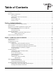
Table of Contents Chapter 1: Introduction and Overview . . . . . . . . . . . . . . . . . . . . . . . . . . . . . . . . . . . . . . . . . . . . . . . . . . 5 Overview . . . . . . . . . . . . . . . . . . . . . . . . . . . . . . . . . . . . . . . . . . . . . . . . . . . . . . . . . . . . . . . . . . . . . . . . . . . . . . . 5 FCC Compliance Information . . . . . . . . . . . . . . . . . . . . . . . . . . . . . . . . . . . . . . . . . . . . . . . . . . . . . . . . . . . . . . . 6 FCC Class B . . . . . . . . . .
Table of Contents Landis+Gyr Chapter 4: Setting Up and Managing in Command Center . . . . . . . . . . . . . . . . . . . . . . . . . . . . . . . . . .43 Command Center Setup . . . . . . . . . . . . . . . . . . . . . . . . . . . . . . . . . . . . . . . . . . . . . . . . . . . . . . . . . . . . . . . . . . .43 C6400-Series Collector Communication . . . . . . . . . . . . . . . . . . . . . . . . . . . . . . . . . . . . . . . . . . . . . . .43 Collector Auto-registration . . . . . . . . . . . . . . . . . . . .
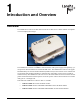
1 Introduction and Overview Overview The C6400-Series Collector is a RF mesh network device that serves a smaller number of endpoints in rural and deployment fringes. Figure 1 - 1. C6400-Series Collector The C6400 Series collector is a NEMA-4 sealed enclosure with a power supply, backup battery, system processor board and hosts one Gridstream IWR radio.
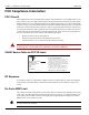
Chapter 1 - Introduction and Overview Landis+Gyr FCC Compliance Information FCC Class B This equipment has been tested and found to comply with the limits for a Class B digital device, pursuant to Part 15 of the FCC Rules. These limits are designed to provide reasonable protection against harmful interference in a residential installation.
Landis+Gyr Chapter 1 - Introduction and Overview Industry Canada The term "IC:" before the radio certification number only signifies that Industry Canada technical specifications were met. This Class B digital apparatus meets all requirements of the Canadian Interference Causing Equipment Regulations.
2 Backhaul Configuration SIM Card Installation for the C6420 Collector A subscriber identification module (SIM) is a smart card that securely stores the service-subscriber key (IMSI) used to identify a subscriber on mobile telephony devices (such as mobile phones, computers and C6400-Series Collectors). Contact your local cellular carrier to obtain an Industrial Grade SIM card for each C6420 Collector to be installed.
Chapter 2 - Backhaul Configuration Landis+Gyr Required Tools for SIM Card Installation and Activation The following tools are required for SIM Card installation and activation. • Industrial grade SIM card • Torque Wrench • Endpoint Testing Manager (ETM) version 5.5.
Landis+Gyr Chapter 2 - Backhaul Configuration U WARNING: DO NOT DISCONNECT BATTERY PACK FROM CARRIER BOARD. The battery will not operate if is disconnected and reconnected. 2 1 3 6 4 Remove Bolts, Nuts and Washers 5 Figure 2 - 2. Bolt Locations U WARNING: Care must be taken to not disturb any other components inside the enclosure. DO NOT UNPLUG ANY CONNECTIONS WITHIN THE ENCLOSURE. Disconnecting and reconnecting of components will cause serious communication issues.
Chapter 2 - Backhaul Configuration Landis+Gyr SIM Card Slot Gasket Figure 2 - 3. SIM Card Location 2. Install the SIM Card A. Locate the slot for the SIM card. B. Align the SIM card with the marking on the slot. The gold contacts of the SIM card face down toward the contacts of the slot. Figure 2 - 4. Align SIM Card to SIM Card Slot C. Carefully slide SIM card in until fully inserted.
Landis+Gyr Chapter 2 - Backhaul Configuration Figure 2 - 5. SIM Card Properly Inserted 3. Close the C6400-Series Collector A. Make sure that the gasket is on the base side of the enclosure to aid in proper alignment of the top lid, see Figure 2 - 3. B. Shut lid enclosure onto base enclosure. NOTE: Ground cable and battery cable must be fully within the inside of the enclosure while it is closed. C. Replace bolts, washers and nuts, see Figure 2 - 6.
Chapter 2 - Backhaul Configuration Landis+Gyr 2 1 3 6 4 5 Figure 2 - 6. Replace Bolts, Washers and Nuts and Tighten Backhaul Configuration Modem Setup for C6420 and C6430 Collectors Modem Setup Overview This Procedure requires the use of an external Gridstream RF IWR radio and Endpoint Testing Manager (ETM) version 5.5.7 or later, running on an external PC or laptop computer. 14 • Attached both antennas to the C6400-Series Collector. • Attach antenna to the IWR.
Landis+Gyr Chapter 2 - Backhaul Configuration • External IWR should be powered ON when the C6400-Series Collector is powered up to allow time for radios to synchronize. • C6400-Series Collector must be within the cellular network providers service area for the activation to work correctly. • Account must be provisioned within the carrier’s cellular network in advance of activation. NOTE: C6400-Series Collectors are shipped with the default Network ID setting of 670.
Chapter 2 - Backhaul Configuration Landis+Gyr Figure 2 - 8. Get WAN Nodes List The WAN Nodes list will open, see Figure 2 - 9. 6. Select the radio of target C6400-Series Collector and push Test Module button located at the top of the screen. Figure 2 - 9. WAN Nodes Information NOTE: When the radio of the C6400-Series Collector is successfully contacted, the Collector tab will become available. If the procedure times out, press the Start Test button on the Device Test tab. C6420 Modem Setup 1.
Landis+Gyr Chapter 2 - Backhaul Configuration IWR should be powered ON when the C6400-Series Collector is powered up to allow time for radios to synchronize. NOTE: C6400-Series Collectors are shipped with the default Network ID setting of 670. The external IWR radio used to communicate with the C6400-Series Collector must also be set at 670. 1. Turn the power strip switch to ON. 2. Note the LAN ID of the C6400-Series Collector. 3. Using ETM on an external PC, connect to an external IWR radio.
Chapter 2 - Backhaul Configuration Landis+Gyr 4. Once logged in, the ETM application connects to the previously connected serial port automatically. If it is not connecting, click on the Connection Tab and then choose the available serial port from the drop-down menu. Choose the COM port from the drop-down menu and then click on Connect. Verify Enable Field Mode in application settings is selected. NOTE: Before connecting confirm that you are in Field Mode. Figure 2 - 10. 5.
Landis+Gyr Chapter 2 - Backhaul Configuration Figure 2 - 12. WAN Nodes Information NOTE: When the radio of the C6400-Series Collector is successfully contacted, the Collector tab will become available. Figure 2 - 13. Collector Tab 10. On the Collector tab, the following Modem Settings will be populated, see Figure 2 - 13: Confirm the presence of a SIM Card by looking at the ICC ID and IMSI entries. Confirm the entries match the account. These entries should not say Check SIM. A.
Chapter 2 - Backhaul Configuration Landis+Gyr F. Revision: Modem revision. G. ICC ID: SIM Card ICC ID H. IMSI: SIM Card IMSI I. Status: RASCS_OpenPort, S_OK. This message confirms that the modem is currently disabled. NOTE: If any fields say Check SIM, an error has occurred in the installation of the SIM card. Contact Landis+Gyr Customer Support at 1-888-390-5733. 11. Select the Settings.... button, see Figure 2 - 13. The Modem Configuration window will open. Figure 2 - 14.
Landis+Gyr Chapter 2 - Backhaul Configuration Figure 2 - 15. Modem Status A CAUTION: If the value noted for Battery Voltage states Error, contact Landis+Gyr Technical Support at 1-888-390-5733. This condition indicates that the battery pack became disconnected or other communication issues have occurred. As a result, battery stats will display erroneous values. C6430 Verizon CDMA Modem Setup 1. Complete steps 1-6 in section See “Connect to the C6400-Series Collectors using ETM” 2.
Chapter 2 - Backhaul Configuration Landis+Gyr Figure 2 - 16. Initiate Verizon Service 3. Once the activation process has been initiated, wait at least 5 minutes for the over the air programming of the NAM to occur. Once completed, press the Settings button Figure 2 - 16. 4. The Modem Configuration information box will open.These settings are for reference only and will not be editable. Check the Enable Internet data connection for the cellular modem check-box and select Send. Figure 2 - 17.
Landis+Gyr Chapter 2 - Backhaul Configuration Figure 2 - 18. Enable Modem 6. Wait approximately 3-5 minutes for the C6400-Series Collector to reboot. Once this time has elapsed, attempt to Fetch All again, Figure 2 - 16. The status will change to RASCS_Connected, S_OK when the unit is successfully connected to the cellular network. Figure 2 - 19. Connected to Cellular Network C6430 Sprint CDMA Modem Setup 1. Complete steps 1-6 in section See “Connect to the C6400-Series Collectors using ETM” 2.
Chapter 2 - Backhaul Configuration Landis+Gyr Figure 2 - 20. Initiate Sprint Service 3. The Activation Settings information box will open displaying the Modem Configuration settings, Figure 2 - 21. Enter the Mobile IP settings obtained from the cellular service provider. Check the Enable Internet data connection for the cellular modem check-box and select Send. Figure 2 - 21. Modem Configuration Settings 4. Wait approximately 3-5 minutes for the C6400-Series Collector to reboot.
Landis+Gyr Chapter 2 - Backhaul Configuration Figure 2 - 22. Connected to Cellular Network Ethernet Setup for C6400 Collectors The utility determines the best configuration to connect the collector to the network.
3 C6400-Series Collector Installation Pre-Installation Overview Proper planning and thorough preparation are critical to successful C6400-Series Collector installation. This chapter outlines basic requirements for the pre-installation phase of the C6400Series Collector deployment process. Safety Overview Prior to starting the installation process, you must develop and launch an installer safety training plan for initial, refresher, and ongoing safety training.
Chapter 3 - C6400-Series Collector Installation Landis+Gyr Table 1. Pre-Install Checklist Item Description Obtain Necessary Permits When the C6400-Series Collector is to be installed on utility or municipal property such as utility poles, there is a general agreement to install on these poles. There may be a requirement for the utility or municipality to approve individual sites. It is the installer's responsibility to ensure that approval has been given for each installation.
Landis+Gyr Chapter 3 - C6400-Series Collector Installation Additional Tools Required for Building and Structure Installs • Steel banding tool • Hammer drill • Bits Installation Material and Third Party Supplies The installation process consists of using predetermined route information identifying C6400-Series Collectors that need to be installed and methods for recording data to document the installation. From the Cross-Dock, obtain C6400-Series Collector and installation kits to install.
Chapter 3 - C6400-Series Collector Installation Landis+Gyr Power Requirements Power requirements are listed in Product Specifications. Verify that the power source is 120V240VAC single phase. Power Cable Preparation You can use the following AC power cable options with any Landis+Gyr mounting kits. Cable part numbers are: • 19-2207. Cable Assy, Power Cable, 10ft • 19-2286. Cable Assy, Power Cable, 20 ft • 19-2280. Cable Assy, Street Light, 6 ft • 19-2281.
Landis+Gyr Chapter 3 - C6400-Series Collector Installation Kit Part Numbers Different kinds of installs may require different mounting and install kits. The following table contains a list of part numbers by installation type. This document details each kit in the appropriate install description. Table 2. Mounting Kits Kit Number Description 45-1211 Collector C6400: Mounting Kit, Street Light Arm, 18 ft. Cable 45-1212 Collector C6400: Mounting Kit, Utility Pole, 20 ft.
Chapter 3 - C6400-Series Collector Installation Landis+Gyr Utility Pole Mounting Kit In addition to the C6400-Series Collector assembly kit, you need a mounting kit. 45-1212 45-1214 45-1367 45-1141 Table 4. Utility Pole Mounting Kit Part Number Name Qty 01-1311 Antenna, Modem 1 106119-000 Antenna-Whip 1 19-1332 Cable Assy, Modem Antenna 1 19-2270 Cable Assy, Ethernet, External, 18 ft. 1 19-2286 Cable Assy, Power Cable, 20 ft.
Landis+Gyr Chapter 3 - C6400-Series Collector Installation When mounting, align the bracket so that the C6400 Series Collector does not exceed 5o off perpendicular to the ground Figure 3 - 2. Bracket, Wood Pole Arm NOTE: When mounting the bracket, align the bracket so that the C6400-Series Collector does not exceed 5o off perpendicular to the ground. 2. Attach the C6400-Series Collector to the bracket. Use the four (4) carriage bolts, washers, lock washers and nuts included in the kit.
Chapter 3 - C6400-Series Collector Installation Landis+Gyr Figure 3 - 3. Attach C6400-Series Collector to the Bracket 4. Kits 45-1141 and 45-1367 Only. Attach the Modem Cable Assembly directly to the C6400-Series Collector and bracket lid. A. Remove hardware from N-bulkhead connector of modem cable. B. Secure the connector to the bracket by applying 100 +/- 10 in. lb. torque to hex nut. C. Attach modem antenna to the N-Bulkhead connector. D.
Landis+Gyr Chapter 3 - C6400-Series Collector Installation Figure 3 - 4.
Chapter 3 - C6400-Series Collector Installation Landis+Gyr 5. Attach the bracket lid to the bracket arm using washers, lock washers and screws provided with the kit. See Figure 3 - 5. Torque screws to 45 +/- 5.0 in. lbs. Figure 3 - 5. Attach Lid to Base 6. Attach the power cable assembly, secure power cable to bracket arm with cable tie provided in the kit. Figure 3 - 6. Figure 3 - 6.
Landis+Gyr Chapter 3 - C6400-Series Collector Installation 7. Kits 45-1212 and 45-1214 Only. Attach the ethernet cable assembly, secure ethernet cable to bracket arm with the cable tie provided in the kit. Figure 3 - 7. Attach Ethernet Cable, Secure with Cable Tie 8. Attach the whip antenna to the bottom of the C6400-Series Collector. Figure 3 - 8.
Chapter 3 - C6400-Series Collector Installation Landis+Gyr Streetlight Arm Horizontal Mount Installation The utility or municipality determines the final guidelines of where to install the C6400-Series Collector. Know and follow the utility or municipality guidelines before installing the C6400-Series Collector and antennas. C6400-Series Collector Streetlight Arm Mounting Kit In addition to your chosen C6400-Series Collector assembly kit, you need a mounting kit.
Landis+Gyr Chapter 3 - C6400-Series Collector Installation Cable Tie, 5.6 Inch Length, UV, Nylon, Black 1 45-1213 30-0055 45-1211 Name 45-1180 Part Number 45-1140 Quantity Table 5. Mounting Kit, Streetlight Arm Streetlight Arm Installation Procedure 1. Attach the C6400-Series Collector to the streetlight enclosure using the bolts, spacers, washers and lock washers included in the kit. Figure 3 - 9 Torque to 45 +/- 5.0 in. lb. Figure 3 - 9. Attach to Streetlight Enclosure 2.
Chapter 3 - C6400-Series Collector Installation Landis+Gyr 3. Attach streetlight bracket to streetlight arm or optional wood pole mounting bracket using Vbolts, washers, lock washers and nuts provided in the kit. Figure 3 - 10. Torque to 45 +/- 5.0 in. lb. 4. Attach streetlight enclosure containing C6400-Series Collector to the streetlight bracket using hex head bolts, washers and lock washers provided in the kit. Figure 3 - 10. Torque to 140 +/- 10.0 in. lb. 5. Kits 45-1140 and 45-1180 Only.
Landis+Gyr Chapter 3 - C6400-Series Collector Installation Figure 3 - 10.
Chapter 3 - C6400-Series Collector Installation Landis+Gyr 6. Kits 45-1211 and 45-1213 Only. Attach the ethernet cable assembly. See Figure 3 - 11. 7. Attach power cable assembly. See Figure 3 - 11. Power Cable Ethernet Cable Figure 3 - 11. Attach Ethernet and Power Cables 8. Attach the whip antenna to the bottom of the C6400-Series Collector.
4 Setting Up and Managing in Command Center Command Center Setup The C6400-Series Collector acts as the gateway between Command Center and the endpoints in the Gridstream network. The C6400-Series Collector provides the interface for sending commands to endpoints and getting readings from endpoints. Prior to receiving readings from endpoints, C6400Series Collectors must be established in Command Center.
Chapter 4 - Setting Up and Managing in Command Center Landis+Gyr Following is the procedure for completing the registration process: 1. From Command Center home, select Setup > Collectors. The Manage Collectors window will open. 2. Click the link for the desired C6400-Series Collector. 3. Click the General Settings tab. Figure 4 - 2. Collector General Settings 4. Enter the following fields: A. RF Collector Name. Enter the C6400-Series Collector Name. This name must be unique to the organization. B.
Landis+Gyr Chapter 4 - Setting Up and Managing in Command Center C. Choose NTP Poll Interval and move to Selected column by selecting the “>” symbol. D. Enter NTP Poll Interval = 8 Figure 4 - 3. Collector Manage Tab 8. Click Send. Collector Time Sync Request 9. From the Manage tab A. From the Command List, select Collector NTP Time Sync. B. Click Send Figure 4 - 4. Collector NTP Time Sync Collector Time Sync Verification 10. From the Manage tab A.
Chapter 4 - Setting Up and Managing in Command Center Landis+Gyr Figure 4 - 5. Collector Command Response D. The Collector - Command Response window will open. E. Review the General Application Statistics • Confirm the current collector time is correct and that the time change was under 10 seconds. • If the collector time is not correct, issue the Collector NTP Time Sync command again. Time Keeper Flag/CRC/Registration ID 11. From the Manage tab: A.
Landis+Gyr Chapter 4 - Setting Up and Managing in Command Center Figure 4 - 6. Modify C6400-Series Collector Settings 12. Click Send. The C6400-Series Collector configuration is complete. C6400-Series Collector General Settings Tab Figure 4 - 7. General Settings Tab General Settings • RF Collector Name. The name must be unique among all active Collectors.
Chapter 4 - Setting Up and Managing in Command Center Landis+Gyr NOTE: Collector names may not contain any spaces. • Status. Indicates the current status of the collector: Normal, Discovered, Inactive. • RF Collector ID. Represents the MAC address of the C6400-Series Collector. This field is automatically populated on C6400-Series Collectors discovered in Command Center. • Time Zone. Enter the time zone for the location of the C6400-Series Collector • Longitude.
Landis+Gyr Chapter 4 - Setting Up and Managing in Command Center Figure 4 - 8. Manage Collectors Tab 4. Select from among the following commands. Collector Commands Ping The Ping command may be issued from the manage tab. It returns a response window populated with the C6400-Series Collector firmware version. The response will appear in new browser window for immediate viewing, or the response can be viewed at a future time from the C6400Series Collector statistics tab.
Chapter 4 - Setting Up and Managing in Command Center Landis+Gyr Modify Collector Settings The Modify Collector Settings command will allow the user to select the desired settings from a drop-down list, and allow a configuration change to be sent to the C6400-Series Collector. Echo Message This command functions much like a PING command, however, the purpose of the command is to be able to send varying sized packets to test the link between Command Center and the endpoint.
Landis+Gyr Chapter 4 - Setting Up and Managing in Command Center Figure 4 - 9. Statistics Tab • Status. The Status section will display the number of endpoints that are in each of the different statuses. Clicking on any of the links in the Status section will open the Endpoint by Status window. • Events/Alerts. The Events/Alerts section summarizes several different endpoint-related errors that could cause a problem with obtaining proper billing data. • Statistics.
Chapter 4 - Setting Up and Managing in Command Center Landis+Gyr History Tab The Collector History tab will display the most recent events and errors that the C6400-Series Collector has logged. By default, the last fifty events and errors are displayed. Figure 4 - 10. History Tab • The list can be filtered by selecting the radio button for 50, 100 or all to view the events and errors for the desired time frame. • Click any of the event or error links to view further details. Figure 4 - 11.
5 Using Endpoint Testing Manager Access to Endpoint Test Manager With the release of Command Center 5.0, ETM users must be authenticated into Command Center prior to accessing the ETM application and communicating with devices in the network. The designated Security Administrator for the utility is responsible for configuring the connection to the Command Center server, and providing log in credentials (including user names and passwords) for those who will require access to the software.
Chapter 5 - Using Endpoint Testing Manager 54 Landis+Gyr Field Description Update Collector S/W...
Landis+Gyr Chapter 5 - Using Endpoint Testing Manager Collector Tab - Identification sub-tab Figure 5 - 1. Collector Tab - Identification sub-tab Identification sub-tab MAC Address A Media Access Control Address is a unique identifier assigned to the connected C6400-Series Collector by the manufacturer for identification. It may also be known as a hardware address or physical address. IP Address Displays the IP Address (unique Internet identity) of the connected C6400-Series Collector.
Chapter 5 - Using Endpoint Testing Manager Landis+Gyr Identification sub-tab Serial Number The electronic serial number of the modem. For GSM this is IMEI. For CDMA this is either ESN or MEID. Status The status of the modem's data connection plus the result of the dial attempt to the network. Provider An attempt to determine which carrier the modem is associated with. If "Unknown" we are unable to determine this. Activate
Landis+Gyr Chapter 5 - Using Endpoint Testing Manager Basic Configuration sub-tab HEX - Lat/Long Format Select the HEX radio button to display all radio WAN addresses in their encoded 6byte hexadecimal format. Selecting the Latitude/Longitude radio button will display the radio’s WAN address in degrees-minutes-seconds format. Default Geocode Geographic coordinates for the connected C6400-Series Collector. Security Level Levels 0 and 1 are selectable for the connected C6400-Series Collector.
Chapter 5 - Using Endpoint Testing Manager Landis+Gyr Collector Tab - Client Routing sub-tab Figure 5 - 3. Collector Tab - Client Routing sub-tab: Port 29029 Mapped Message Types are listed when a TCP Listening port is highlighted, along with check boxes for these types. Check boxes can individually selected for each port according to configuration preferences. Figure 5 - 4.
Landis+Gyr Chapter 5 - Using Endpoint Testing Manager When the Collector-initiated port is highlighted, the Command Center Address List appears, displaying both the Send and Poll Paths, parameters for Push Data Interval and Maximum Messages per Push, and the Collector to Command Center Queue Status. Client Routing sub-tab TCP Listening Ports Identifies, and allows the user to select access to, the TCP ports for each radio that the collector is connected to.
Chapter 5 - Using Endpoint Testing Manager Landis+Gyr Statistics sub-tab Figure 5 - 7. Statistics sub-tab Statistics sub-tab 60 Current Time Allows a user to insert comments into the Activity Log. These timestamped comments will also list in the Log file. Application Running Time The amount of time the collector application has been running. Boot Count The number of times the collector application has started. Time Changes A list of the most recent adjustments to the collector's system clock.
A Specifications Specifications Table 1. C6400-Series Collector Element Description Electrical/Power Supply Supply Voltage 96 - 277 Vrms Power Consumption 9W typical - batteries not charging 18W typical - batteries charging Gridstream Radio, General Frequency Range 902 - 928 MHz Channels 240 or 85 (depending on mode) Modulation FSK/GFSK Baud Rates 9.6, 19.2, 38.4 kbps (100kHz channels), 9.6, 19.2, 38.4, 50, 115.2 kbps (300kHz channels) Frequency Deviation 4.95 to 57.
Appendix A - Specifications Landis+Gyr Table 1. C6400-Series Collector Max RF Input Power (no damage) 15 dBm RSSI Accuracy: ±6 dB Backhaul Modem GSM/GPRS/EDGE Frequency Bands: 850/900/1800/1900 MHz Standards: E-GPRS class 12, GPRS class 12 Data Rate: Packet data up to 240 kbps (modulation & coding scheme, MCS 1-9, mobile station class B) EV-DO Frequency Bands: 800/1900 MHz Standards: EV-DO Rev A/CDMA2000 1xRTT Data Rate: Peak Downlink up to 3.1 mbps/Peak Uplink up to 1.
Landis+Gyr Appendix A - Specifications C6400-Series Collector Dimensions 10.864” 7.70” 1.097” 7.802” 5.869” 4.72” 3.73” 6.965” 3.92” 3.10” 1” Typ 3.125” 4.614” 0.84” 5.84” 5.04” 1.46” 4.01” 9.30” Figure A - 1.
B Cable Installation Power Connection and Termination Figure B - 1. Improper Power Termination U WARNING: If using the 19-2207 or 19-2286 cables, the end of the cable opposite the connector (the unterminated end) must be installed in a junction box, other suitable enclosure, or drip loops at both ends of the cable should be provided. Leaving the end of the cable exposed may allow water to migrate into the cable and into the C6400-Series Collector.
Appendix B - Cable Installation Landis+Gyr In published examples, collector cables are shown going through conduit. Conduit is not required for C6400-Series Collectors, but the entrance to the junction box should be through a clamp at the bottom of the junction box. Junction boxes do not have a part number and are available through local vendors. As always, electrical connections need to meet the requirements of the local utility and local ordinances.
Landis+Gyr Appendix B - Cable Installation Direct Cable Installation to Main X F R M Wrap wires with mastic tape or other method of protecting from the weather P O L E Min 6” Loop Outer jacket may be exposed where wires join 19-2207 or 19-2286 cable C6400- Series Collector DRIP LOOP Figure B - 3.
Appendix B - Cable Installation Landis+Gyr Ethernet Cable Installation X F R M P O L E X F R M P O L E Min 6” Loop Communications Cabinet Ethernet Cable Communications Cabinet Ethernet Cable C6400- Series Collector DRIP LOOP C6400-Series Collector DRIP LOOP Figure B - 4.