Certification Exhibit FCC ID: R7PWGRS4 FCC Rule Part: 15.247 ACS Report Number: 09-0421.W03.11.A Manufacturer: Cellnet Technology, Inc. Model: Gridstream Wangate Manual 5015 B.U.
Landis+Gyr Series IV Gridstream RF Router User and Installation Guide D ra ft 3. 15 .
Limitation on Warranties and Liability Information in this document is subject to change without notice. This manual or any part of it thereof may not be reproduced in any form unless permitted by contract or by written permission of Landis+Gyr.
Table of Contents Chapter 1: Gridstream Series IV Router . . . . . . . . . . . . . . . . . . . . . . . . . . . . . . . . . . . . . . . . . . . . . . . . . 5 Overview . . . . . . . . . . . . . . . . . . . . . . . . . . . . . . . . . . . . . . . . . . . . . . . . . . . . . . . . . . . . . . . . . . . . . . . . . . . . . 5 Notes on International version . . . . . . . . . . . . . . . . . . . . . . . . . . . . . . . . . . . . . . . . . . . . . . . . . . . . . . . . . . . . .
Table of Contents Landis+Gyr Chapter 5: Gridstream Router and Component Specifications . . . . . . . . . . . . . . . . . . . . . . . . . . . . . . .35 Gridstream Router Component Details . . . . . . . . . . . . . . . . . . . . . . . . . . . . . . . . . . . . . . . . . . . . . . . . . . . . . 35 AC Power Cables . . . . . . . . . . . . . . . . . . . . . . . . . . . . . . . . . . . . . . . . . . . . . . . . . . . . . . . . . . . . . . . . . . . . . . 35 DC Power/Programming Cables . . . . . . . . . . . . . .
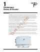
1 Gridstream Series IV Router Overview 01 0 The Landis+Gyr Gridstream Router is designed for outdoor mounting. The Gridstream Router supports RS-232/485 serial interface for Transparent Packet Protocol (TPP) and RS-232 serial interface for LAN Packet Protocol (LPP). The LAN Packet Protocol line is used to communicate to devices which use LPP, such as a PC with configuration or diagnostic software, or an end device which has implemented LPP.
Chapter 1 - Gridstream Series IV Router Landis+Gyr The Gridstream Router radio is provided in a white, die-cast aluminum enclosure. It has two connectors—one for AC power and one for RS-232/485 signal and 12/24 DC power. The Gridstream Router will operate between 120VAC (+/-20%) and 277 VAC (+/-15%) without having to change any settings. 12/24 VDC can be applied through the same port that provides the RS-232 lines. RS-232 lines are provided for both LPP and TPP communication.
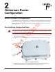
2 Gridstream Router Configuration Direct Connect Configuration 01 U .2 Pre-Installation Configuration Steps 0 The Gridstream Router, when shipped to the customer, may require configuration prior to network deployment. Occasionally it may be necessary to update the configuration before the Gridstream Router is installed. See “Gridstream Router Parts and Materials” on page 28 for a list of optional programming cables.
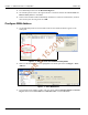
Chapter 2 - Gridstream Router Configuration Landis+Gyr 4. From RadioShop home select the Head-End Mgmt tab. 5. Click the drop-down arrow to the right of the Discover button and then select Force Scan and Discover Entry Ports or click Start. 6. Select which available COM Port RadioShop should use to check for attached radios, uncheck those Comm ports not being used. Click OK. Configure WAN Address 3. 15 .2 01 0 1.
Chapter 2 - Gridstream Router Configuration 0 Landis+Gyr 01 Figure 2 - 4. Configure WAN Address Window After clicking the OK button, the WAN Address Change confirmation dialog box will appear. D ra ft 3. 15 .2 4. Click both boxes to check-mark Clear Current Reports and Run Radio Configuration Report. Click the OK button. Figure 2 - 5. WAN Address Change Window The WAN Address will be displayed in the Radio Information window. Figure 2 - 6.
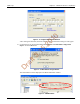
Chapter 2 - Gridstream Router Configuration Landis+Gyr Setting the Network ID To assign the Network ID to the Gridstream Router, perform the following steps. All Landis+Gyr Gridstream radios, including the Gridstream Router, ship with a default network ID, or CRC, of 670. 1. Select Configure > Change Network Id (CRC)..., the Network ID Wizard is displayed. 3. 15 .2 01 0 2. Select Use an Existing Network. Click Next. Figure 2 - 7. Network ID Wizard Window D ra ft 3.
Landis+Gyr Chapter 2 - Gridstream Router Configuration If you have not been assigned a Network ID, contact Landis+Gyr customer service. 0 4. The Final Confirmation window will open. Click Next. 01 Figure 2 - 9. Final Confirmation Window ft 3. 15 .2 A confirmation message verifies that the new Network ID has been assigned to the radio. Click Finish to return to RadioShop. ra Figure 2 - 10. Click Finish to Finalize Configuration 5.
Landis+Gyr 0 Chapter 2 - Gridstream Router Configuration 01 Figure 2 - 11. Enable Routing Figure 2 - 12. Routing Enabled D ra ft 3. 15 .2 4. RadioShop will reboot the Gridstream Router and a new Radio Configuration Report will be generated. Scroll down through the new report and confirm that the routing bit is enabled. “Y” indicates that the routing bit IS enabled. Download New Firmware Firware upgrades can be accomplished by several different methods.
Chapter 2 - Gridstream Router Configuration 01 0 Landis+Gyr .2 Figure 2 - 13. Select Baud Rate 15 Direct Connection Firmware Download 1. Make sure the Gridstream Router is selected in the Nodes pane. D ra ft 3. 2. Select Configure > Firmware > Download New Firmware.... The NMP Configuration window will open. Figure 2 - 14.
Chapter 2 - Gridstream Router Configuration Landis+Gyr 3. Select the Use This PC radio button. Choose the firmware version to download under the Part Number drop-down menu arrow. 4. After selecting the firmware version, click the OK button. After the firmware download begins, the Get Download Information dialog box opens. Click the No button. 5. The Get Download Information dialog closes and the Download Progress window displays a progress bar. When the action concludes, close RadioShop. 6.
Landis+Gyr Chapter 2 - Gridstream Router Configuration 4. Once connected, the local radio's LAN address will appear on the list at the top left-hand side of the screen, and a radio configuration report will be displayed in the main window. Figure 2 - 16. Local Radio LAN Address In the example above, the Network Id of the Local Radio is 450. It must be changed to 670 to be able to communicate with a new Gridstream Router.
Chapter 2 - Gridstream Router Configuration Landis+Gyr 3. Specify 670 or Gridstream Router’s ID for both the Network ID and Name of the new network, and click Next to continue. Figure 2 - 18. Network ID 670 15 .2 01 0 4. The Final Confirmation window will open. Click Next. 3. Figure 2 - 19. Final Confirmation Window D ra ft 5. A confirmation message verifies that the new Network ID has been assigned to the radio. Click Finish to return to RadioShop. Figure 2 - 20.
Landis+Gyr Chapter 2 - Gridstream Router Configuration Adding New Radios to RadioShop You can now add the Gridstream Router to the RadioShop database. 1. Make sure your local radio is highlighted on the Nodes Pane. 2. Click Generate WAN Nodes Report. 0 3. From RadioShop home click Utilities > Radio > Discover Neighbors. Figure 2 - 22. Discovering Neighbors 3. 15 .2 01 4. Once discovered, the Gridstream Router’s LAN Address will show up on the Nodes pane. Figure 2 - 23.
ft ra D 0 01 .2 15 3.
3 Series IV Routers in Command Center Importing Routers into Command Center 01 Generating the Import Installation File (IIF) 0 The following section describes the process of manually importing Routers into Command Center. The minimum data set required to successfully import the Router into Command Center includes: Wan ID, User ID, Installation Date, Installation Time, Installed Meter No, Installed Endpoint SN, and Service Time Zone. 15 .
Chapter 3 - Series IV Routers in Command Center Landis+Gyr CSV File Fields UserID: 1 (Router default) • InstallationDate: Local Date (preferably collected by installer when operation performed). • InstallationTime: Local Time (preferably collected by installer when operation performed). • ChangeOutMeterNo: N/A • ChangeOutMeterkWh: N/A • InstalledMeterNo: ID assigned by the Network Engineers. • InstalledEndpointSN: Serial number of the Router in decimal.
Landis+Gyr Chapter 3 - Series IV Routers in Command Center Time Zone In order to report readings time correctly, the router must be programmed with the appropriate time zone. This is achieved by sending commands to the router that indicates the time zone in which the endpoint is installed and whether Daylight Savings Time (DST) is observed in the given time zone. The meter installer should include the endpoint time zone in the Installation File.
Chapter 3 - Series IV Routers in Command Center Landis+Gyr RF Network Settings The RF Network Settings establish organization level settings for outage wait values, time synchronization, etc. The RF Network Settings are a part of the endpoint configuration and may only be changed by Landis+Gyr technical support. Command Center Operation Router This function allows the user to remove a deployed router from service. The removed router can either be put back into inventory or archived. 01 2.
Chapter 3 - Series IV Routers in Command Center 01 0 Landis+Gyr Figure 3 - 7. Remove Endpoint From Service .2 5. Enter Removed Electric Meter Information: A. Enter the Final kWh Reading (Optional) 15 B. Enter the Final Reading Date (Optional) 3. C. Enter Removed Endpoint Information. Select a reason for the removal from the drop down list box. D. Awaiting Redeployment. This option will transition the endpoint to Inventory status. ft E. Permanently Remove From Service.
ft ra D 0 01 .2 15 3.
4 Installation Best Practices Gridstream Router Installation The final guidelines provided by the utility or municipality determine where the Gridstream Router can be installed. It is the installer’s responsibility to know and follow the utility or municipality guidelines before installing the Gridstream Router.
Landis+Gyr 01 0 Chapter 4 - Installation Best Practices .2 Figure 4 - 1. Gridstream Router Installed on a Swivel Bracket 15 Gridstream Router Parts and Materials 3. When receiving system components, carefully inspect the packaging and contents for any damage, and file any necessary damage claims with the shipper. The table below lists Gridstream Routerrelated installation parts. (However, not all parts will necessarily be needed in every installation.) Table 4-1.
Landis+Gyr Chapter 4 - Installation Best Practices Table 4-1.
Chapter 4 - Installation Best Practices Landis+Gyr Table 4-1. Gridstream Router Parts and Materials Part Number Qty Gridstream Router Mounting Kit 45-1081 1 Washer,1/4 Flat,1/16 Thk, SS 22-0421 4 Washer,1/4 Slit Lock,1/ 16 Thk,SS 22-0422 4 Washer,Flat,3/8IDx.81ODx1/16,SS 22-0452 6 Bolt, Hex Head, 3/8-16x6.0 inch, Fully Threaded, SS 22-1116 4 Bolt, Hex Head, 3/8-16x1.0 inch, SS 22-1117 2 Bolt, Hex Head, 1/4-20x2.
Landis+Gyr Chapter 4 - Installation Best Practices 40” Minimum Below Conductor 30” Minimum Below Transformer 01 0 RF Router Installation Location Communications Cables (if present) 3. 15 30” Minimum Above Communications Cables .2 18” Min. As High as Possible D ra ft 30” Minimum Below Communications Cables Figure 4 - 2. Gridstream Router Mounting Overview Above-Conductor Gridstream Router Installation Above conductor router installation components and minimum distances. 1.
Chapter 4 - Installation Best Practices Landis+Gyr D ra ft 3. 15 .2 01 0 4. UGuard, 1”, length as required. Figure 4 - 3.
Landis+Gyr Chapter 4 - Installation Best Practices Installation Overview 1. The Gridstream Router mounting kit may be preassembled for ease of installation on a streetlight mast. 2. Slide a lock washer and a flat washer onto each of the two 3/8-16 bolts, attach the swivel bracket to the mounting plate by threading bolt into press nut on mounting plate. 3.
Chapter 4 - Installation Best Practices Landis+Gyr VERIFY this street light has power 24/7 and is NOT remotely switched 15 .2 01 0 Gridstream Router Mounting Kit 45-1018 D ra ft 3. Figure 4 - 4.
Landis+Gyr Chapter 4 - Installation Best Practices ft 3. 15 .2 01 0 Gridstream Router Mounting Kit 45-1081 D ra Figure 4 - 5.
ft ra D 0 01 .2 15 3.
5 Gridstream Router and Component Specifications Gridstream Router Component Details If using the 105704-000, 105704-001, 105704-002, 105704-003, or 19-1224 cables, the end of 01 U 0 AC Power Cables the cable opposite the connector (the unterminated end) must be installed in a junction box or other suitable enclosure. .2 Leaving the end of the cable exposed may allow water to migrate into the cable and into the Gridstream Router.
Chapter 5 - Gridstream Router and Component Specifications Landis+Gyr 10’ Unterminated #10 SJO Two Wires (P/N 105627-000) This Gridstream Router AC power cable (see Figure 5 - 2) is 10 feet long and is split into two #10 wires. Disconnecting the power cable at the radio will also disconnect the battery in a battery backed Gridstream Router radio. CONNECTOR END VIEW enlarged to show detail 0 J1 INTERCONNECTION DIAGRAM 01 J1 BLACK BLACK A B C D E .2 Figure 5 - 2.
Landis+Gyr Chapter 5 - Gridstream Router and Component Specifications 6’ Terminated AC Plug (P/N 105628-000) This Gridstream Router AC power cable (see Figure 5 - 4) is 6 feet long and terminates in an AC plug. It is used to plug into an AC outlet. Since the Gridstream Router is usually wired directly to AC with one of the unterminated cables (see P/N 105704-00X and P/N 105627-000) in a final installation, this cable is typically only used for demonstration and test purposes.
Chapter 5 - Gridstream Router and Component Specifications Landis+Gyr DC Power/Programming Cables RS-232 Signal & DC Power Cable, 10’ Unterminated (P/N 105552-000) 15 .2 01 0 This Gridstream Router cable (see Figure 5 - 6) connects to the RS-232 port of the radio and provides access to the RS-232 lines for both Gridstream LAN Packet Protocol communication and transparent port data. In addition, it also furnishes the lines to power the Gridstream Router with 12/ 24 VDC.
Landis+Gyr Chapter 5 - Gridstream Router and Component Specifications RS-232 Programming Cable 10’ Terminated w/12V vehicle adapter plug (105616-000) This Gridstream Router cable (see Figure 5 - 8) connects to the RS-232 port of the radio and provides access to the RS-232 line, the Gridstream LAN Packet Protocol Port and the RS-232/485 Transparent Port. It is 10 feet long and terminated in two Female DB-9 connectors for easy programming connection and a 12 volt vehicle adapter plug for power. 3. 15 .
Chapter 5 - Gridstream Router and Component Specifications Landis+Gyr Battery Replacement Kit (P/N 45-1027) 3. 15 .2 01 0 A battery (see Figure 5 - 10) is provided for backup during a power outage. If a Gridstream Router radio is initially ordered without a battery, a battery kit can be ordered later. The battery kit can also be ordered when the battery has to be replaced. ft Figure 5 - 10.
Landis+Gyr Chapter 5 - Gridstream Router and Component Specifications Gridstream Router Radio Specifications D ra ft 3. 15 .2 01 0 Gridstream Router Dimensions Figure 5 - 11.
Chapter 5 - Gridstream Router and Component Specifications Landis+Gyr 3. 15 .2 01 0 Gridstream Router Pinout ra ft Figure 5 - 12. Gridstream Router Pinout D Gridstream Router International Pinout Figure 5 - 13.
Landis+Gyr Chapter 5 - Gridstream Router and Component Specifications Specifications Tables Table 5-1. Gridstream RF Router Specifications Electrical Power Supply Input AC Voltage 96-317 VAC Input Current, Receive mode, 120 VAC Operation 15 mA (max) Input Current, Transmit mode, 120 VAC Operation 95 mA peak, 25 mA average Input Current, Battery charging, 120 VAC operation 30 mA (max) RF Frequency Range 902-928 MHz (U.S.
Chapter 5 - Gridstream Router and Component Specifications Landis+Gyr Table 5-1. Gridstream RF Router Specifications Data Bits 8 Stop Bits 1 Duplex Full Transparent Port RS-232C/RS-485 Protocol Any asynchronous byte-oriented protocol Parity None Data Bits 7 or 8 Stop Bits 1 or 2 Duplex Full 01 Environmental Operating Temperature Range -40 to 85 C (internal ambient of enclosure) -40 to 85 C .2 Storage Temperature Range Operating Vibration ANSI C12.1 ANSI C12.
A Regulatory Compliance FCC (Part 15.247) This device complies with Part 15 of the FCC Rules. Operation is subject to the following two conditions: 0 1. This device may not cause harmful interference, and 01 2. This device must accept any interference received, including interference that may cause undesired operation. A 15 .2 Changes or modifications not expressly approved by Landis+Gyr for compliance could void the user’s authority to operate the equipment. FCC Class B 3.
ft ra D 0 01 .2 15 3.
B Power Cable Installation U Figure B - 1. Improper Power Termination D ra ft 3. 15 .2 01 0 Power Connection and Termination If using the 105704-000, 105704-001, 105704-002, 105704-003, or 19-1224 cables, the end of the cable opposite the connector (the unterminated end) must be installed in a junction box or other suitable enclosure. Leaving the end of the cable exposed may allow water to migrate into the cable and into the Gridstream Router.
Appendix B - Power Cable Installation Landis+Gyr Recommendations When existing 105704-XXX cables are used, they must be terminated inside a junction or disconnect box. The inner wires cannot be exposed until after the 105704-XXX cable enters the enclosure. Once inside the box, connect the power leads to wires going to the mains per local practice. Connections to the mains must use UV-stable wiring.
C Troubleshooting Troubleshooting Gridstream Routers The following are general guidelines for troubleshooting a router once it has been successfully installed and configured for communications to the Command Center head-end system. 0 A router's main purpose is to facilitate routing of packets and provide communications paths. If a router fails, the network will self adjust and use alternative communications paths.
Landis+Gyr 01 0 Appendix C - Troubleshooting Figure C - 2. Ping Command .2 4. If Command Center fails to establish communications with the router, validate that the pole top or the street light that the router is mounted on has power. 15 5. Use RadioShop to try to establish communications with the router through a neighboring collector and/or a meter. 6. If the problem persists, contact Landis+Gyr field services for further investigation and replace the faulty router with a new one. 3.