Model 2000 Series Row Crop Cultivator Operator’s Manual LANDOLL CORPORATION 1900 North Street Marysville, Kansas 66508 (785) 562-5381 800-428-5655 ~ WWW.LANDOLL.
Table of Contents 1 Introduction Understanding Safety Statements . . . . . . . . . . . . . . . . . . . . . . . . . . . . . . . . . . . . . . . . . . . . . . . . 1-2 2 Standard Specifications 3 Assembly Instructions Assembly Preparation . . . . . . . . . . . . . . . . . . . . . . . . . . . . . . . . . . . . . . . . . . . . . . . . . . . . . . . . . . 3-1 Wing Fold Plumbing Installation . . . . . . . . . . . . . . . . . . . . . . . . . . . . . . . . . . . . . . . . . . . . . . . . .
Ridgers and Knives . . . . . . . . . . . . . . . . . . . . . . . . . . . . . . . . . . . . . . . . . . . . . . . . . . . . . . . . . . . . 4-8 Shields . . . . . . . . . . . . . . . . . . . . . . . . . . . . . . . . . . . . . . . . . . . . . . . . . . . . . . . . . . . . . . . . . . . . . . . 4-9 Lift Assist Wheel . . . . . . . . . . . . . . . . . . . . . . . . . . . . . . . . . . . . . . . . . . . . . . . . . . . . . . . . . . . . . . . 4-9 Tool Hold Down Springs . . . . . . . . . . . . . . . . . . . . . .
Chapter 1 Introduction The Landoll Model 2000 Series Row Crop Cultivator is a quality product designed to give years of trouble free performance. By following each section of this manual, your system will perform as designed for you and your operation CHAPTER 1 gives basic instructions on the use of this manual. CHAPTER 2 gives product specifications. These specifications supply lengths and measures for your equipment.
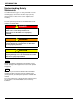
INTRODUCTION Understanding Safety Statements You will find various types of safety information on the following pages and on the machine signs (decals) attached to the vehicle. This section explains their meaning. The Safety Alert Symbol means ATTENTION! YOUR SAFETY IS INVOLVED! DANGER Danger means a life-threatening situation exists. Death can occur if safety measures or instructions on this label are not properly followed.
Chapter 2 Standard Specifications 2000 SERIES ROW CROP CULTIVATOR RIGID MODELS MODEL NO. 2004-30HC-94 2004-36HC-94 2006-30HC-94 2006-36HC-94 2008-30HC-94 2008-36HC-94 2008-40HC-94 2010-30HC-94 NO. OF ROWS 4 4 6 6 8 8 8 10 TRANSPORT WIDTH 11’-0” 13’-8” 16’-0” 20’-0” 21’-0” 26’-4” 27’-8” 26’-0” NO. OF SHANKS 5 5 7 7 9 9 9 11 NO. OF COULTERS 5 5 7 7 9 9 9 11 SHANK SPACING 30” 36” - 38” 30” 36” - 38” 30” 36” - 38” 40” 30” ESTIMATED WEIGHT (LBS.
STANDARD SPECIFICATIONS LANDOLL CORPORATION GENERAL TORQUE SPECIFICATIONS (REV. 4/97) THIS CHART PROVIDES TIGHTENING TORQUES FOR GENERAL PURPOSE APPLICATIONS WHEN SPECIAL TORQUES ARE NOT SPECIFIED ON PROCESS OR DRAWING. ASSEMBLY TORQUES APPLY TO PLATED NUTS AND CAPSCREWS ASSEMBLED WITHOUT SUPPLEMENTAL LUBRICATION (AS RECEIVED CONDITION). THEY DO NOT APPLY IF SPECIAL GRAPHITE MOLY-DISULFIDE OR OTHER EXTREME PRESSURE LUBRICANTS ARE USED.
STANDARD SPECIFICATIONS LANDOLL CORPORATION HYDRAULIC FITTING TORQUE SPECIFICATIONS 37o JIC, ORS, & ORB (REV. 10/97) THIS CHART PROVIDES TIGHTENING TORQUES FOR HYDRAULIC FITTING APPLICATIONS WHEN SPECIAL TORQUES ARE NOT SPECIFIED ON PROCESS OR DRAWING. ASSEMBLY TORQUES APPLY TO PLATED CARBON STEEL AND STAINLESS STEEL FITTINGS ASSEMBLED WITHOUT SUPPLEMENTAL LUBRICATION (AS RECEIVED CONDITION). THEY DO NOT APPLY IF SPECIAL GRAPHITE MOLY-DISULFIDE OR OTHER EXTREME PRESSURE LUBRICANTS ARE USED.
STANDARD SPECIFICATIONS 2-4 F-140-0512 Edition
Chapter 3 Assembly Instructions It is very important that your new 2000 Series Row Crop Cultivator be properly assembled, adjusted and lubricated before use. Illustrations to assist with the assembly process are provided in Section 2, “Standard Specifications”. They show proper shank, disc gang and mounting bracket spacings. Illustrations in this section show proper assembly procedures. Remove paint from grease fittings. Replace any grease fittings that are damaged or missing.
ASSEMBLY INSTRUCTIONS HOSE B HOSE E HOSE A 90º RESTRICTOR FITTING HOSE D HYDRAULIC CYLINDER TOOL MOUNT U-BOLT TOOL BAR TOOL FRAME MOUNTING ANGLE 3/4-10 HEX LOCK NUT 1/2-13 X 3-1/2 HEX HEAD CAP SCREW HOSE C HOSE E HOSE D 1/2-13 HEX LOCK NUT PLUG 1/2 FLAT WASHER 2mc809-010082 op HYDRAULIC MANIFOLD MOUNTING BRACKET HOSE A HOSE B HYDRAULIC MANIFOLD Figure 3-1: Hydraulic Installation Wing Fold Plumbing Installation IMPORTANT See Figure 3-1 and Table 3-1 for parts names.
ASSEMBLY INSTRUCTIONS 2000 SERIES HYDRAULIC HOSE TABLE ITEM A PART NUMBER HOSE LENGTH USED ON MODEL 1-397-010299-14 24" 2008-30HCF-94 1-397-010299-15 48" 2006-36HCF-94, 2008-36HCF-94, 2008-40HCF-94 1-397-010299-06 56" 2010-30HCF-94, 2010-30HCFLG-94, 2012-30HCF-94 1-397-010299-12 84" 2010-36HCF-94, 2010-38HCF-94, 2012-36HCF-94, 2012-40HCF-94, 2016-30HCF-94 1-397-010299-19 90" 2012-38HCF-94 1-397-010299-15 48” 2008-30HCF-94 1-397-010299-13 74” 2008-40HCF-94 1-397-010299-18 68” 2006
ASSEMBLY INSTRUCTIONS DISC HILLER BRACKET SPACER TUBE (END TOOL FRAMES ONLY) 1/2-13 HEX LOCK NUT WEEDING DISC LOCK PIN 1/8 HAIR PIN CLEVIS PIN TOOL FRAME MOUNT OFFSET WEED DISC ASSEMBLY WEDGE CASTING 1/2-13 X 8-1/2 HEX HEAD CAP SCREW 545ma014585 op Figure 3-2: Disc Installation Disc Installation IMPORTANT See Figure 3-2 for parts names. When assembly is done, tighten all fastening hardware to the torques listed in Table 2-1 and Table 2-2.
ASSEMBLY INSTRUCTIONS 1/2-13 X 3-1/2 HEX HEAD CAP SCREW TOOL MOUNT FRAME BRACKET 1/2-13 FLANGE HEAD SERRATED NUT 1/2-13 FLANGE HEAD SERRATED NUT MIDDLE GAUGE WHEEL ASSEMBLY (INNER FRAMES) 1/2-13 X 3-1/2 HEX HEAD CAP SCREW END GAUGE WHEEL ASSEMBLY (OUTER FRAMES) 2000 gauge wheel assembly Figure 3-3: Gauge Wheel Installation Gauge Wheel Installation IMPORTANT See Figure 3-3 for parts names. When assembly is done, tighten all fastening hardware to the torques listed in Table 2-1 and Table 2-2.
ASSEMBLY INSTRUCTIONS 3/4-10 X 3 HEX HEAD CAP SCREW 5/8-11 HEX LOCK NUT TOOL MOUNT FRAME 3/4-10 HEX LOCK NUT LONG SHANK SHANK U-BOLT 1/2-13 X 2-1/2 PLOW BOLT 1/2 FLAT WASHER 1/2 SPLIT LOCK WASHER SWEEP 1/2-13 HEX NUT 545m104598 Figure 3-4: Shank Installation Shank Assembly IMPORTANT See Figure 3-4 for parts names. When assembly is done, tighten all fastening hardware to the torques listed in Table 2-1 and Table 2-2. Tighten u-bolts evenly to show an even amount of thread on both legs of the u-bolt.
ASSEMBLY INSTRUCTIONS TOOL MOUNT FRAME 1/2-13 X 8 HEX HEAD CAP SCREW COULTER FORK PLATE 1/2-13 X 8-1/2 HEX HEAD CAP SCREW 1/2-13 X 2 HEX HEAD CAP SCREW 3/4-10 HEX LOCK NUT 1/2-13 HEX LOCK NUT COULTER FORK ASSEMBLY COULTER BRACE 545m104383 op Figure 3-5: Coulter Blade Installation Coulter Blade Installation IMPORTANT See Figure 3-5 for parts names. When assembly is done, tighten all fastening hardware to the torques listed in Table 2-1 and Table 2-2.
ASSEMBLY INSTRUCTIONS SHIELD MOUNTING BRACKET FRAME TOOL MOUNT SHANK SHANK U-BOLT SHANK TOP VIEW ASSEMBLED 545m104649 op Figure 3-6: Shield Installation (Option) Shields 1. Mount the shield bracket centered over the shank (See Figures 3-4 and 3-6) during shank installation. (See “Shank Assembly” on page 3-6.) 2. Install the shank u-bolt over the shank, through the frame tool mount and the shield mounting bracket. Secure with 5/8-11 hex lock nuts.
ASSEMBLY INSTRUCTIONS FERTILIZER ATTACHMENT U-BOLT 5/16-18 HEX LOCK NUT OFFSET DISC ASSEMBLY FERTILIZER TUBE ASSEMBLY PLASTIC TUBE END 5/8-11 HEX LOCK NUT SHANK U-BOLT AMMONIA KNIFE ASSEMBLY 545m104602 IRRIGATION RIDGERS (OPTION) RIDGER ASSEMBLY Figure 3-7: Optional Accessories Installation Ridgers Anhydrous Ammonia Knives A ridger is an optional device that can be installed on each shank. 1. The ammonia knives are mounted in the same manner as the ridgers.
ASSEMBLY INSTRUCTIONS 5/8-11 X 3 HEX HEAD CAP SCREW MAIN FRAME MOUNTING BRACKET 5/8-11 SPLIT LOCK WASHER 5/8-11 HEX NUT lift assist wheel op LIFT ASSIST WHEEL Figure 3-8: Lift Assist Wheel Installation Lift Assist Wheel WARNING An escaping hydraulic oil under pressure can produce enough force to penetrate the skin, causing serious personal injury.
ASSEMBLY INSTRUCTIONS 1-8 HEX NUT 1/2-13 X 1 HEX HEAD CAP SCREW PARALLEL LINKAGE BOLT FRAME TOOL MOUNT 1/2-13 HEX JAM NUT SPRAY MOUNT BRACKET SPRAY NOZZLE ARM MOUNT 1/4-20 X 1-1/2 HEX HEAD CAP SCREW 1/4-28 HEX LOCK NUT SPRAY NOZZLE MOUNT ARM MOUNTING BAR ATTACH SPRAY NOZZLES AND HOSES HERE 1/4-20 HEX LOCK NUT 1/4-28 X 1 HEX HEAD CAP SCREW SPRAY NOZZLE BAR 545m104650 op Figure 3-9: Spray Nozzle Mount Installation Spray Nozzle Mount Attachment The optional spray nozzle attachment adds a spray acces
ASSEMBLY INSTRUCTIONS 5/8-11 TOOL MOUNT U-BOLT 5/8 FLAT WASHER 5/8-11 HEX LOCK NUT HITCH FRAME WELDMENT 3/4-10 HEX LOCK NUT TOOL FRAME BAR TOOL FRAME MOUNT 3/4-10 U-BOLT HITCH WELDMENT 545m104766 op HITCH ASSEMBLY Figure 3-10: Nurse Tank Hitch Installation Nurse Tank Hitch Assembly IMPORTANT See Figure 3-10 for parts names. 1. Set tool frame bar on support stands. 2. Attach the hitch frame weldment to the tool frame bar by straddling it around the center tool frame mount assembly.
ASSEMBLY INSTRUCTIONS 1 2 5 6 3 4 7 1 1 9 8 5 6 8 2 4 3 7 3 12 10 4 6 2 5 3 6 1 4 9 11 11 9 10 12 2000B row crop decals Figure 3-11: Decal Installation 3-13
ASSEMBLY INSTRUCTIONS Decal Placement Decals are extremely important for naming purposes and for alerting others to the presence of the machine. PLACE ALL DECALS on the cultivator as shown in Figure 3-11. Center them as nearly as possible between the top and bottom on the frame bar. Sometimes, shank spacing may position a tool frame too near the end of the frame bar to place a reflective tape square exactly as shown.
ASSEMBLY INSTRUCTIONS Notes: 3-15
ASSEMBLY INSTRUCTIONS 3-16 F-140-0512 Edition
Chapter 4 Operation and Maintenance DANGER Never allow anyone to ride on the 2000 Series Row Crop Cultivator at any time. Allowing a person to ride on the machine can inflict serious personal injury or death to that person. DANGER Coulter blades are extremely sharp. Exercise extreme care when working on or near disc blades. Do not allow discs to roll over or fall onto any bodily part. Do not allow wrenches to slip when working near disc blades. Never push wrenches toward disc blades.
OPERATION AND MAINTENANCE Tractor Preparation Cultivator Preparation The 2000 Series Row Crop Cultivator may be used on tractors equipped with category II or III three-point hitches with quick couplers. Before attaching the cultivator, prepare the tractor as follows: The rear tractor tires should be inflated equally and ballast added according to the tractor operator’s manual. 1.
OPERATION AND MAINTENANCE TO TOP HOLE OF TRACTOR THE RIDGER SHOULD BE LEVEL WITH THE TOP OF THE SWEEP TOP HOLE LEVEL TOP HOLE 6TH LINK FROM TOP SET WEEDING DISC AT 15º 2” GROUND LEVEL 1” 1-1/2” 2m573-010323 Figure 4-2: Recommended Settings for Initial Setup Initial Setup 1. Set the tractor and cultivator on a cement or other hard, level surface, and check that the top adjustment link is greased and easy to operate. 2. Lower the cultivator until the sweeps contact the surface.
OPERATION AND MAINTENANCE Field Operation 1. Remove the stabilizer bars or sway blocks from the drawbar assembly on the tractor. 2. Pull the cultivator a few feet at the approximate desired depth and speed you intend to maintain during use.
OPERATION AND MAINTENANCE Gauge Wheel Adjustment 1/2-13 X 3-1/2 HEX HEAD CAP SCREW TOOL MOUNT FRAME BRACKET Coulter Adjustment 1/2-13 HEX LOCK NUT TOOL MOUNT FRAME 1/2-13 FLANGE HEAD SERRATED NUT 1/2-13 X 8-1/2 HEX HEAD CAP SCREW 1/2-13 X 2 HEX HEAD CAP SCREW gauge wheel adjust Figure 4-3: Gauge Wheel Adjustment 1. For stability, the gauge wheels must always apply slight pressure against the soil. Adjust the gauge wheels by raising or lowering, as needed, to reach proper depth.
OPERATION AND MAINTENANCE COTTER PIN 4 BOLT HUB SPINDLE WASHER HEX SLOTTED NUT DISC HILLER BRACKET SPACER TUBE (END TOOLS ONLY) 1/4-28 HEX JAM NUT DUST CAP GREASE ZERK 1/2-13 HEX LOCK NUT WEEDING DISC LOCK PIN 1/8 HAIR PIN CLEVIS PIN DISC BLADE 1/2-20 X 1 HEX HEAD CAP SCREW INNER CONE BEARING CUP TOOL FRAME MOUNT INNER BEARING CONE WEDGE CASTING OFFSET SPINDLE WELDMENT 1/2-13 X 8-1/2 HEX HEAD CAP SCREW OFFSET WEED DISC ASSEMBLY 545m104585 Figure 4-5: Disc Adjustment 4-6 F-140-0512 Edition
OPERATION AND MAINTENANCE Disc Adjustment Disc Bearing Maintenance Adjust the disc to the proper depth and pitch to create the desired weeding effect. Discs working at different settings from each other tend to make the machine fight itself. Also, discs working too deeply into the soil tend to throw up excess dirt, resulting in root pruning, which causes the sweeps to plug. To adjust the discs (See Figure 4-5): Check all roller bearings occasionally for excess end play.
OPERATION AND MAINTENANCE Tool Frame 3/4-10 U-BOLT 1. The length of up and down movement for the tool frame is controlled by the limit chain (See Figure 4-6) on the left side of the tool frame. If a different distance of movement is required, change the limit chain one link at a time until the desired amount of movement is met. IMPORTANT A longer limit chain setting will result in less ground clearance when the machine is lifted out of the ground. LIMIT CHAIN 7/16-14 HEX LOCK NUT Ridgers and Knives 1.
OPERATION AND MAINTENANCE Shields WIDTH ADJUSTMENT SCREW Adjust the shields by moving the shield adjustment chain up or down one link at a time until the desired height is reached (See Figure 4-8.) The shield width can be adjusted by loosening the adjustment screws and sliding the shields in or out to the desired width. Tighten the adjustment screws. Lift Assist Wheel Adjust the optional lift assist wheel so that when the machine is in use, the lift assist wheel is lifted clear of the ground.
OPERATION AND MAINTENANCE Tool Hold Down Springs Lubrication The hold down springs are on either side of the parallel linkage on the tool frames and are factory adjusted for most normal conditions. Tightening the springs increases the ground tool pressure. Too much pressure will shorten the life of the ground tools. See Figure 4-10 for lubrications points and recommended maintenance schedule. Hydraulic Maintenance 1.
OPERATION AND MAINTENANCE Storage The service life of the cultivator will be extended by the following proper off-season storage practices: 1. Completely clean the unit and inspect the machine for worn or defective parts. Replace defective and worn parts, as needed, to avoid delays the following season. 2. Repaint all areas where the original paint film is worn off. 3. Grease all exposed metal surfaces of shanks, points, and coulters. 4. Lubricate as suggested in “Lubrication” on page 4-10. 5.
OPERATION AND MAINTENANCE 4-12 F-140-0512 Edition
Chapter 5 Troubleshooting Guide The Troubleshooting Guide, shown below, is included to help you quickly locate problems that can happen using your 2000 Series Row Crop Cultivator. Follow all safety precautions stated in the previous sections when making any adjustments to your machine. PROBLEM PROBABLE CAUSE SOLUTION SWEEPS NOT PENETRATING THE SOIL Tool bar, parallel linkage, and sweeps are not set properly.
TROUBLESHOOTING GUIDE Notes: 5-2 F-140-0512 Edition
Equipment from Landoll Corporation is built to exacting standards ensured by ISO 9001:2008 registration at all Landoll manufacturing facilities. Model 2000 Series Row Crop Cultivator Operator’s Manual Re-Order Part Number F-140-0512 LANDOLL CORPORATION 1900 North Street Marysville, Kansas 66508 (785) 562-5381 800-428-5655 ~ WWW.LANDOLL.COM Copyright 2010.