
Owner manual


3-4 F-140-0512 Edition
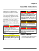
ASSEMBLY INSTRUCTIONS
Figure 3-2: Disc Installation
Disc Installation
IMPORTANT
See Figure 3-2 for parts names. When assembly is
done, tighten all fastening hardware to the torques
listed in Table 2-1 and Table 2-2. Tighten u-bolts
evenly to show an even amount of thread on both
legs of the u-bolt.
IMPORTANT
The outer tool frames have a disc blade only on the
inside of the tool frame. The outside has a spacer
tube installed instead of the disc hiller bracket.
1. Remove the clevis pin and hair pin from each disc
hiller bracket.
2. Insert a disc blade and spindle assembly through
each disc hiller bracket to the desired depth.
Reinstall the clevis pin and hair pin.
SPACER TUBE
(END TOOL FRAMES ONLY)
1/2-13 HEX LOCK NUT
WEEDING DISC LOCK PIN
1/8 HAIR PIN
CLEVIS
PIN
OFFSET WEED
DISC ASSEMBLY
DISC HILLER
BRACKET
TOOL FRAME
MOUNT
WEDGE CASTING
1/2-13 X 8-1/2 HEX
HEAD CAP SCREW
545ma014585 op