
Manual


ASSEMBLY INSTRUCTIONS
3-3
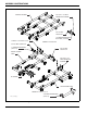
2111-07/09 Frame Assembly
1. No assembly is needed for the 2111-07 or 2111-09
frame. However, it needs to be placed on stands
about 36" high in an open, level area.
2. If you have a 2111-09 Coulter Chisel, attach the 1
shank frame extensions using 3/4-10 x 2-1/4 hex
head cap screws and hex lock nuts. See Figures 2-3
thru 2-4 for extension locations.
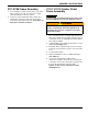
2111-11/13/15 Coulter Chisel
Frame Assembly
IMPORTANT
Read all safety precautions at the front of the section
before attempting any of the following procedures.
WARNING
1. Place both frame halves on stands approximately 36”
high. The assembly area should be a large level area
of sufficient size to accommodate the Coulter Chisel
when fully assembled.
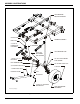
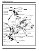
2. Install bushings in the cylinder anchor plates on each
frame half (See Figure 3-1.)
3. Bolt frame halves together using 3/4-10 x 2-1/4 hex
head cap screws and hex lock nuts. Leave all screws
loose.
4. Level the frame halves.
5. Tighten all hardware to the recommended torques
(See Table 2-1.)
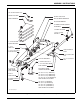
6. If your 2111 Coulter Chisel requires frame
extensions, install the extensions by securing them
to the tubes on the sides of the frame using 3/4-10 x
6 x 6-13/16 u-bolt and hex lock nuts. See
Figures 2-5 thru 2-10 for extension locations
and dimensions.
Do not attempt to lift heavy parts (such as the
frame, coulter gangs, wheel lift, and pull hitch)
manually. Use a hoist or a forklift to move these
parts into position.