Model 2410 Weatherproofer I Operator’s Manual LANDOLL CORPORATION 1900 North Street Marysville, Kansas 66508 (785) 562-5381 800-428-5655 ~ WWW.LANDOLL.
Table of Contents 1 Introduction Understanding Safety Statements . . . . . . . . . . . . . . . . . . . . . . . . . . . . . . . . . . . . . . . . . . . . . . . . 1-2 2 Standard Specifications 3 Assembly Instructions Weatherproofer I Frame Assembly . . . . . . . . . . . . . . . . . . . . . . . . . . . . . . . . . . . . . . . . . . . . . . . . 3-3 Wheel Lift Installation . . . . . . . . . . . . . . . . . . . . . . . . . . . . . . . . . . . . . . . . . . . . . . . . . . . . . . . . . .
Disc Blades . . . . . . . . . . . . . . . . . . . . . . . . . . . . . . . . . . . . . . . . . . . . . . . . . . . . . . . . . . . . . . . . . . . 4-5 Depth Stop Adjustment (Manual) . . . . . . . . . . . . . . . . . . . . . . . . . . . . . . . . . . . . . . . . . . . . . . . . . 4-5 Wheel Bearing Maintenance . . . . . . . . . . . . . . . . . . . . . . . . . . . . . . . . . . . . . . . . . . . . . . . . . . . . . 4-6 Hydraulic Maintenance . . . . . . . . . . . . . . . . . . . . . . . . . . . . . . . . . . . .
Chapter 1 Introduction The Landoll Model 2410 Weatherproofer I is a quality product designed to give years of trouble free performance. By following each section of this manual, your system will perform as designed for you and your operation CHAPTER 1 gives basic instructions on the use of this manual. CHAPTER 2 gives product specifications. These specifications supply lengths and measures for your equipment.
INTRODUCTION Understanding Safety Statements You will find various types of safety information on the following pages and on the machine signs (decals) attached to the vehicle. This section explains their meaning. The Safety Alert Symbol means ATTENTION! YOUR SAFETY IS INVOLVED! DANGER Danger means a life-threatening situation exists. Death can occur if safety measures or instructions on this label are not properly followed.
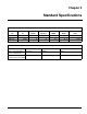
Chapter 2 Standard Specifications 2410 Series Weatherproofer I Model No. No. of Blades F/r 2410-6-24 2410-7-24 2410-9-24 No. of Shanks 16/18 18/20 22/22 Shank Spacing 6 7 9 24” 24” 24” Transport Width 15’-4” 17’-4” 19’-6” Working Width 12’-0” 14’-0” 18’-0” Estimated Weight (Lbs.) 14,560 15,822 17,010 Tire Inflation Tire Size 12.5L x 15 Heavy Duty (Used on 2410-6-24) Tire Manufacturer Goodyear 380/55R 16.
STANDARD SPECIFICATIONS LANDOLL CORPORATION GENERAL TORQUE SPECIFICATIONS (REV. 4/97) THIS CHART PROVIDES TIGHTENING TORQUES FOR GENERAL PURPOSE APPLICATIONS WHEN SPECIAL TORQUES ARE NOT SPECIFIED ON PROCESS OR DRAWING. ASSEMBLY TORQUES APPLY TO PLATED NUTS AND CAPSCREWS ASSEMBLED WITHOUT SUPPLEMENTAL LUBRICATION (AS RECEIVED CONDITION). THEY DO NOT APPLY IF SPECIAL GRAPHITE MOLY-DISULFIDE OR OTHER EXTREME PRESSURE LUBRICANTS ARE USED.
STANDARD SPECIFICATIONS LANDOLL CORPORATION HYDRAULIC FITTING TORQUE SPECIFICATIONS 37o JIC, ORS, & ORB (REV. 10/97) THIS CHART PROVIDES TIGHTENING TORQUES FOR HYDRAULIC FITTING APPLICATIONS WHEN SPECIAL TORQUES ARE NOT SPECIFIED ON PROCESS OR DRAWING. ASSEMBLY TORQUES APPLY TO PLATED CARBON STEEL AND STAINLESS STEEL FITTINGS ASSEMBLED WITHOUT SUPPLEMENTAL LUBRICATION (AS RECEIVED CONDITION). THEY DO NOT APPLY IF SPECIAL GRAPHITE MOLY-DISULFIDE OR OTHER EXTREME PRESSURE LUBRICANTS ARE USED.
STANDARD SPECIFICATIONS 4-7/8 4-7/8 7-7/8 3-3/8 22-1/2 8-1/8 7-7/8 8-1/8 3-3/8 22-1/2 2410-6 shank placement Figure 2-1: Shank and Light Bracket Placement Assembly (2410-6-24) 2-4 F-620-0912 Edition
STANDARD SPECIFICATIONS 6-3/8 2-3/8 6-3/8 10-3/8 10-3/8 6-3/8 2-3/8 2410-7 shank placement Figure 2-2: Shank and Light Bracket Placement Assembly (2410-7-24) 2-5
STANDARD SPECIFICATIONS 6-3/8 2-3/8 8-7/16 8-7/16 2-3/8 10-3/8 22-1/2 6-3/8 4-5/16 10-3/8 2-1/2 2-1/2 22-1/2 2410-9 shank placement Figure 2-3: Shank and Light Bracket Placement Assembly (2410-9-24) 2-6 F-620-0912 Edition
STANDARD SPECIFICATIONS 7-21/32 7-21/32 35-3/8 35-3/8 2410-6-24 20-5/32 20-5/32 45-31/32 45-31/32 2410-7-24 12-3/32 43-3/16 12-3/32 2410-9-24 43-3/16 m171128 finishing combo placement Figure 2-4: Finishing Combo w/ Chopper Reel Installation 2-7
STANDARD SPECIFICATIONS 7-21/32 7-21/32 35-3/8 35-3/8 20-5/32 20-5/32 45-31/32 45-31/32 2410-7-24 11-5/8 11-5/8 43-3/16 m172492 finishing combo cond reel placement 43-3/16 2410-9-24 Figure 2-5: Finishing Combo w/ Conditioner Reel Installation 2-8 F-620-0912 Edition
STANDARD SPECIFICATIONS 35 35 2410-6-24 43-31/32 43-31/32 2410-7-24 43-3/4 m171126 finishing chopper placement 43-3/4 2410-9-24 Figure 2-6: Finishing Chopper Reel Installation 2-9
STANDARD SPECIFICATIONS 35-3/8 35-3/8 P/N 172497 (2410-6-24) 43-31/32 43-31/32 P/N 172498 (2410-7-24) 43-3/4 43-3/4 P/N 172499 (2410-9-24) m172497 finishing cond reel placement Figure 2-7: Finishing Conditioner Reel Installation 2-10 F-620-0912 Edition
STANDARD SPECIFICATIONS 8-11/32 8-11/32 2410-6-24 20-3/8 20-3/8 2410-7-24 12-3/32 m171127 finishing harrow placement 12-3/32 2410-9-24 Figure 2-8: Finishing Harrow Installation 2-11
STANDARD SPECIFICATIONS 2-12 F-620-0912 Edition
Chapter 3 Assembly Instructions It is very important that your new 2410 Weatherproofer I be properly assembled, adjusted and lubricated before use. Illustrations to assist with the assembly process are provided in “Standard Specifications” on page 2-1. They show proper shank and light mounting bracket spacing. Illustrations in this section show proper assembly procedures. Remove paint from grease fittings. Replace any grease fittings that are damaged or missing. Be sure to return screws, clips, etc.
ASSEMBLY INSTRUCTIONS RH FRAME ASSEMBLY 1-1/2 X 16 LOCKOUT CYLINDER STOP L-PIN 1/8 HAIRPIN FRAME JOINT PLATE 3/4-10 X 11 HEX HEAD CAP SCREW 3/4-10 HEX LOCK NUT FRAME JOINT PLATE 3/4-10 X 6 HEX HEAD CAP SCREW 3/4-10 HEX LOCK NUT LH FRAME ASSEMBLY 3/4-10 X 2-1/4 HEX HEAD CAP SCREW 2410-9 frame assembly Figure 3-1: Frame Assembly 3-2 F-620-0912 Edition
ASSEMBLY INSTRUCTIONS Weatherproofer I Frame Assembly IMPORTANT Read all safety precautions at the front of the section before attempting any of the following procedures. WARNING Do not attempt to lift heavy parts (such as the frame, disc gangs, wheel lift, and pull hitch) manually. Use a hoist or a forklift to move these parts into position. 1. Place both frame halves on stands approximately 36” high.
ASSEMBLY INSTRUCTIONS TIRE AND WHEEL ASSEMBLY WALKING BEAM ASSEMBLY ROCKSHAFT 4” UHMW BEARING LIFT BEARING CAP 2410-6-24 MODEL 3/4-10 X 2 HEX HEAD CAP SCREW 3/4-10 HEX LOCK NUT LEVELING LINKAGE BUSHING 5/16 X 2-1/2 SPRING SLOTTED PIN LIFT PIN WHEEL BOLT TIRE AND WHEEL ASSEMBLY ROCKSHAFT LUG NUT 3/4-10 X 2 HEX HEAD CAP SCREW LIFT BEARING CAP 3/4-10 HEX LOCK NUT 4” UHMW BEARING LIFT BEARING CAP 3/4-10 X 2 HEX HEAD CAP SCREW 3/4-10 HEX LOCK NUT 2410 lift assembly op 2410-7-24 AND 2410-9-24 MODELS
ASSEMBLY INSTRUCTIONS Wheel Lift Installation 1. Place 4” UHMW bearings onto rockshaft. Attach lift bearing caps onto rockshafts using 3/4-10 x 2 hex head cap screws and hex lock nuts. 2. Attach rockshaft to the frame assembly using lift bearing cap, 3/4-10 x 2 hex head cap screws, and hex lock nuts. 3. Attach rod end of each 3-1/2 x 16 (2410-6-24) or 4 x 16 (2410-7-24 & 2410-9-24) hydraulic cylinder to the lift using lift pins and 5/16 x 2-1/2 spring slotted pins (See Figure 3-2.) 4.
ASSEMBLY INSTRUCTIONS LEVELER TUBE 1-1/4N FLAT WASHER HITCH PIN 1-8 HEX LOCK NUT 1/2 X 2-1/4 GROOVED ALLOY PIN 1-1/4 - 7 HEX NUT 1-1/4 - 7 X 8 HEX HEAD CAP SCREW GR8 1-1/4 SPLIT LOCK WASHER LEVELER TOWER 1-1/4 - 7 HEX NUT HITCH RADIUS ROD ASSEMBLY 1-1/4 SPLIT LOCK WASHER FRAME ASSEMBLY 1/4-20 X 1 HEX HEAD CAP SCREW WING NUT CLAMP 3/4-10 FLANGE NUT 3/8-16 HEX NUT 3/8-16 X 3-1/2 ALL THREAD SCREW 1/4-20 HEX LOCK NUT 1-8 X 7-1/2 HEX HEAD CAP SCREW CLEVIS HITCH 1-1/4-7 X 9-1/2 HEX HEAD CAP SCREW JAC
ASSEMBLY INSTRUCTIONS Hitch Installation 1. Attach the hitch weldment to the front of the frame using hitch pins, shims, 1-8 hex lock nuts, and 1/2 x 2-1/4 grooved alloy pins (See Figure 3-3.) NOTE Use shims as required to eliminate slack in the hitch to frame assembly. 2. Move the jack to the forward mounting tube and rotate to parking position to support the front of the hitch. 3.
ASSEMBLY INSTRUCTIONS DEPTH STOP TUBE ASSEMBLY 5/8-11 HEX LOCK NUT DEPTH STOP MOUNT PLATE DEPTH STOP HANDLE 5/8-11 X 2-1/2 HEX HEAD CAP SCREW WHEEL AND LIFT ASSEMBLY 3/8-16 HEX LOCK NUT 3/8-16 X 1-1/4 HEX HEAD CAP SCREW FRAME ASSEMBLY 2410 depth stop tube op Figure 3-4: Depth Stop Assembly Installation 3-8 F-620-0912 Edition
ASSEMBLY INSTRUCTIONS Depth Stop Tube Assembly 1. Attach the depth stop mount plate to the lift using 3/8-16 x 1-1/4 hex head cap screws and hex lock nuts. IMPORTANT It may be necessary to leave these screws loose to attach the valve hoses later. 2. Lay the depth stop tube assembly on top of the center frame. Insert a 5/8-11 x 2-1/2 hex head cap screw in the rear hole of the tube assembly from the left side (See Figure 3-4.
ASSEMBLY INSTRUCTIONS CLAMP PLATE 3/4-10 X 11 HEX HEAD CAP SCREW GR8 FRAME ASSEMBLY 3/4-10 X 2 HEX HEAD CAP SCREW GR8 CLAMP PLATE LEFT REAR DISC GANG ASSEMBLY 3/4-10 HEX LOCK NUT DETAIL A (USED ON 2410-9-24 MODELS LEFT INNER FRONT AND LEFT OUTER REAR DISC GANGS ONLY) FRAME ASSEMBLY RIGHT REAR DISC GANG ASSEMBLY LEFT REAR DISC GANG ASSEMBLY RIGHT FRONT DISC GANG ASSEMBLY SEE DETAIL A 3/4-10 X 2 HEX HEAD CAP SCREW GR8 CLAMP PLATE 3/4-10 X 11 HEX HEAD CAP SCREW GR8 CLAMP PLATE LEFT FRONT DISC GANG A
ASSEMBLY INSTRUCTIONS Disc Gang Installation NOTE See Figures 2-1 thru 2-3 for disc gang placement. DANGER Disc blades are extremely sharp. Exercise extreme care when working on or near disc blades. Do not allow disc to roll over or fall onto any body part. Do not allow wrenches to slip when working near disc blades. Never push wrenches toward disc blades. Do not climb over machine above disc blades. Failure to stay clear of disc blade edges can cause serious personal injury or death. 1.
ASSEMBLY INSTRUCTIONS CLAMP ASSEMBLY 3/4-10 HEX LOCK NUT 5/8-11 HEX LOCK NUT 3/4-10 X 4 HEX HEAD CAP SCREW 5/8-11 X 3-3/4 HEX HEAD CAP SCREW 1-1/4 X 4 BOLT-IN SHANK 5/8 X 3/4 X 1-1/4 CONNEX BUSHING 1-1/4” SHARK FIN POINT 1-1/4” WINGED SUBSOILER POINT 3/8 X 2 SPRING SLOTTED PIN 1-1/4” SHANK V-CAP POINT 2410 shank inst op Figure 3-6: Auto Reset Shank and Shovel Installation 3-12 F-620-0912 Edition
ASSEMBLY INSTRUCTIONS Auto Reset Shank and Shovel Installation 1. Attach each 1-1/4 x 4 bolt-in shank to each clamp assembly using 3/4-10 x 4 hex head cap screw and hex lock nut in the top hole and 5/8-11 x 3-3/4 hex head cap screw, 5/8 x 3/4 x 1-1/4 connex bushing, and hex lock nut in the second hole (See Figure 3-6.) 2. Connect subsoiler points to each shank using 3/8 x 2 spring slotted pins.
ASSEMBLY INSTRUCTIONS 1-1/2 x 16 LOCKOUT 1/8 HAIRPIN CYLINDER STOP L-PIN ADAPTER 45 ADAPTER 90 HOSE CLAMP 4 X 16 HYDRAULIC CYLINDER ADAPTER 3/8 X 48 HOSE ASSEMBLY 3/8 X 67 HOSE ASSEMBLY LIMIT VALVE 1/2 X 96 HOSE ASSEMBLY ADAPTER 90 90 ADAPTER 1/2 X 204 HOSE ASSEMBLY (G) (A) (H) 8 PORT MANIFOLD (B) (D) 3/8 X 103-1/4 HOSE ASSEMBLY 1/2 X 271 HOSE ASSEMBLY (C) 1/2-13 X 3-1/2 HEX HEAD CAP SCREW AND HEX LOCK NUT 3/4-16 MALE COUPLER 3/8 X 86 HOSE ASSEMBLY (A) (B) (G) (E) (H) (F) (C) (D) FRONT O
ASSEMBLY INSTRUCTIONS 1-1/2 x 16 LOCKOUT 1/8 HAIRPIN CYLINDER STOP L-PIN ADAPTER 45 ADAPTER 90 HOSE CLAMP 4 X 16 HYDRAULIC CYLINDER ADAPTER 3/8 X 40 HOSE ASSEMBLY 3/8 X 54 HOSE ASSEMBLY LIMIT VALVE 1/2 X 96 HOSE ASSEMBLY ADAPTER 90 90 ADAPTER 1/2 X 204 HOSE ASSEMBLY (G) (A) (H) 8 PORT MANIFOLD (B) (D) 3/8 X 96 HOSE ASSEMBLY 1/2 X 271 HOSE ASSEMBLY (C) 1/2-13 X 3-1/2 HEX HEAD CAP SCREW AND HEX LOCK NUT 3/4-16 MALE COUPLER 3/8 X 78 HOSE ASSEMBLY (A) (B) (G) (E) (H) (F) (C) (D) FRONT OF MAC
ASSEMBLY INSTRUCTIONS 3/8-16 X 3 OR 3/8-16 X 4 HEX HEAD CAP SCREW HOSE CLAMPS 3/8-16 HEX LOCK NUT 2410 hitch hose clamps Figure 3-9: Hitch Hose Clamps and Color Designation Hydraulic Installation NOTES Refer to Figure 3-7 for hydraulic diagram for the 2410-6-24 model. Refer to Figure 3-8 for hydraulic diagrams for the 2410-7-24 and 2410-9-24 models. 1. Install the manifold to the manifold bracket on the frame using 1/2-13 x 3-1/2 hex head cap screws and hex lock nuts. 4.
ASSEMBLY INSTRUCTIONS FRONT OF MACHINE HARNESS EXTENSION 1/4-20 x 1-1/4 HEX HEAD CAP SCREW YELLOW REFLECTOR ASSEMBLY MAIN WARNING LIGHT HARNESS 1/4-20 HEX LOCK NUT ORANGE STRIPE SINGLE AMBER LAMP REAR WARNING LIGHT HARNESS WIRING HARNESS SPLITTER RED REFLECTOR 1/4-20 X 3/4 HEX HEAD CAP SCREW SMV EMBLEM ORANGE STRIPE 1/4-20 HEX LOCK NUT 1/2-13 HEX LOCK NUT WARNING LIGHT BAR #8-32 X 1/2 SLOT PAN HEAD SCREW RED REFLECTOR YELLOW REFLECTOR ASSEMBLY SINGLE AMBER LAMP 1/2-13 X 5-1/2 HEX HEAD CAP SCREW
ASSEMBLY INSTRUCTIONS FRONT OF MACHINE LH LIGHT BRACKET W/ REFLECTORS MAIN WARNING LIGHT HARNESS YELLOW REFLECTOR SINGLE AMBER LAMP 1/2-13X 9-1/2 HEX HEAD CAP SCREW 1/2-13 HEX LOCK NUT RED REFLECTOR REAR WARNING LIGHT HARNESS HARNESS EXTENSION 1/4-20 HEX LOCK NUT ORANGE STRIPE 1/4-20 X 1-1/4 HEX HEAD CAP SCREW #8-32 X 1/2 SLOT PAN HEAD SCREW 1/4-20 X 3/4 HEX HEAD CAP SCREW ENHANCED LIGHTING MODULE SMV EMBLEM #8-32 HEX NUT 1/2-13 X 5-1/2 HEX HEAD CAP SCREW SMV MOUNTING BRACKET WARNING LIGHT BAR
ASSEMBLY INSTRUCTIONS NOTE: IF REPAIRING OR REPLACING THE 7 PIN CONNECTOR, MATCH THE LETTERS AT THE BACK OF THE HARNESS TO THE 7 PIN CONNECTOR AS SHOWN. THE COLOR OF THE WIRE JACKET DOES NOT NECESSARILY MATCH THE COLOR MARKING OF THE 7 PIN CONNECTOR. #1 WHITE #2 BLACK #3 YELLOW #7 BLUE WIRING CHART 7-PIN CONNECTION 4-PIN CONNECTION GRND. 1 D YEL. 3 B GRN. 5 A BRN.
ASSEMBLY INSTRUCTIONS 1/4-20 X 1-1/4 HEX HEAD CAP SCREW AND HEX LOCK NUT SPLITTER WIRING HARNESS REFLECTOR ASSEMBLY, YELLOW 1/4-20 X 1-1/4 HEX HEAD CAP SCREW AND HEX LOCK NUT 34” EXTENSION HARNESS F MAIN WARNING LIGHT HARNESS REFLECTOR ASSEMBLY HARNESS STOR-AWAY F G REAR WARNING LIGHT HARNESS E AG AMBER SINGLE LED LAMP A G B E H A E E H SMV EMBLEM REFLECTOR ASSEMBLY 1/4-20 X 3/4 HEX HEAD CAP SCREW AND HEX LOCK NUT 1/2-13 X 5-1/2 HEX HEAD CAP SCREW AND HEX LOCK NUT F C H G D SMV BRACKE
ASSEMBLY INSTRUCTIONS WIRE DESIGNATIONS FOR MAIN HARNESS 7-PIN 4-PIN CONN TOWER 1 2 3 4 5 6 7 D B A C CIRCUIT GROUND WORK LAMPS LEFT FLASHING & TURN STOP LAMPS RIGHT FLASHING & TURN TAIL LAMPS SWITCHED POWER (12V) WIRE DESIGNATIONS FOR REAR HARNESS 1 WIRE COLOR 2 3 4 5 2-PIN 3-PIN 6-PIN 3-PIN 2-PIN TOWER TOWER SHROUD TOWER TOWER GROUND BLACK YELLOW A RED GREEN A B B C BROWN BLUE A B C D E C A B A B F m177210 wire designations op Figure 3-14: 7 Pin Connector Detail and Wiring Chart (Afte
ASSEMBLY INSTRUCTIONS 34” EXTENSION HARNESS 1/4-20 X 1-1/4 HEX HEAD CAP SCREW AND HEX LOCK NUT MAIN WARNING LIGHT HARNESS LH LIGHT BRACKET W/ REFLECTORS HARNESS STOR-AWAY 1/2-13 X 9-1/2 HEX HEAD CAP SCREW AND HEX LOCK NUT E A B REFLECTOR ASSEMBLY B E C F A F D E F SMV EMBLEM AG AMBER SINGLE LED LAMP REFLECTOR ASSEMBLY TAIL LIGHT MOUNT 1/4-20 X 1-1/4 HEX HEAD CAP SCREW AND HEX LOCK NUT 1/4-20 X 3/4 HEX HEAD CAP SCREW AND HEX LOCK NUT SMV BRACKET 1/2-13 X 5-1/2 HEX HEAD CAP SCREW AND HEX LO
ASSEMBLY INSTRUCTIONS LED Light and SMV Bracket Installation (2410-6-24 and 2410-9-24) (After August, 2013) NOTES • See Figures 2-1 thru 2-3 for light bracket placement. If no dimension is given for a bracket, it should be located against frame member as shown in drawing. • See Figure 3-15 for Light and SMV Bracket Installation for 2410-6-24 and 2410-9-24 models. IMPORTANT 7. Attach front warning harness to frame.
ASSEMBLY INSTRUCTIONS Final Assembly Rear Jack Installation 1. Attach a tractor to the implement and charge the lift system hydraulics as described in “Hydraulic Lift System” on page 4-3. A rear jack assembly is available for use on the Weatherproofer I combination finishing kits. 2. Install the 1-1/2 x 16 lockouts on both 3-1/2 x 16 cylinders on the frame. 3. Connect lights to the tractor and verify operation. 4. Check tires for proper inflation 1.
ASSEMBLY INSTRUCTIONS (E-2) (E-1) (A) (B) 2-1/2 X 2-1/2 CYLINDER (C) (D) FRONT OF MACHINE ADAPTER, 90 (G) (H) (F-1) (F-2) MANIFOLD HOSE ASSEMBLY 1/4 X 98 ADAPTER, 45 HOSE ASSEMBLY 1/4 X 108 HOSE ASSEMBLY 1/4 X 98 (C) (D) ADAPTER 1/2-13 X 3-1/2 HEX HEAD CAP SCREW AND HEX LOCK NUT (F-1) 8 PORT HYDRAULIC MANIFOLD (E-1) HOSE ASSEMBLY 1/4 X 80 ADAPTER TEE HOSE ASSEMBLY (E-2) 1/4 X 102 ADAPTER, 90 (A) (F-2) (G) (H) (B) ADAPTER 3/8 X 428 HOSE ASSEMBLY 3/4-16 MALE COUPLER WRENCH HARROW ADJUSTMEN
ASSEMBLY INSTRUCTIONS (E-2) (E-1) (A) (B) 2-1/2 X 2-1/2 CYLINDER (C) (D) FRONT OF MACHINE ADAPTER, 90 (G) (H) (F-1) (F-2) MANIFOLD HOSE ASSEMBLY 1/4 X 78 ADAPTER, 45 HOSE ASSEMBLY 1/4 X 104 HOSE ASSEMBLY 1/4 X 90 (C) (D) ADAPTER 1/2-13 X 3-1/2 HEX HEAD CAP SCREW AND HEX LOCK NUT (F-1) 8 PORT HYDRAULIC MANIFOLD (E-1) HOSE ASSEMBLY 1/4 X 64 ADAPTER TEE HOSE ASSEMBLY (E-2) 1/4 X 86 ADAPTER, 90 (A) (F-2) (G) (H) (B) ADAPTER 3/8 X 428 HOSE ASSEMBLY 3/4-16 MALE COUPLER WRENCH HARROW ADJUSTMENT
ASSEMBLY INSTRUCTIONS (E-2) (E-1) (A) (B) 2-1/2 X 2-1/2 CYLINDER (C) (D) FRONT OF MACHINE ADAPTER, 90 (G) (H) (F-1) (F-2) MANIFOLD HOSE ASSEMBLY 1/4 X 84 ADAPTER, 45 HOSE ASSEMBLY 1/4 X 130 HOSE ASSEMBLY 1/4 X 116 (C) (D) ADAPTER 1/2-13 X 3-1/2 HEX HEAD CAP SCREW AND HEX LOCK NUT (F-1) 8 PORT HYDRAULIC MANIFOLD (E-1) HOSE ASSEMBLY 1/4 X 72 ADAPTER TEE HOSE ASSEMBLY (E-2) 1/4 X 90 ADAPTER, 90 (A) (F-2) (G) (H) (B) ADAPTER 3/8 X 428 HOSE ASSEMBLY 3/4-16 MALE COUPLER WRENCH HARROW ADJUSTMEN
ASSEMBLY INSTRUCTIONS 22 NOTE: SIDE PLATE HIDDEN FOR CLARITY.
ASSEMBLY INSTRUCTIONS Finishing Combo w/ Chopper Reel Installation (Option) 3. Install fittings into manifold according to Figures 3-19 thru 3-21. 4. Install hoses per Figures 3-19 thru 3-21. 5. Install steel plugs in any remaining open manifold or valve ports. NOTES Refer to Figure 3-19 for hydraulic diagram for the 2410-6-24 model. Refer to Figure 3-20 for hydraulic diagram for the 2410-7-24 model. Refer to Figure 3-21 for hydraulic diagram for the 2410-9-24 model.
ASSEMBLY INSTRUCTIONS 22 NOTE: SIDE PLATE HIDDEN FOR CLARITY.
ASSEMBLY INSTRUCTIONS Finishing Combo w/ Conditioner Reel Installation (Option) 3. Install fittings into manifold according to Figures 3-19 thru 3-21. 4. Install hoses per Figures 3-19 thru 3-21. 5. Install steel plugs in any remaining open manifold or valve ports. NOTES Refer to Figure 3-19 for hydraulic diagram for the 2410-6-24 model. Refer to Figure 3-20 for hydraulic diagram for the 2410-7-24 model. Refer to Figure 3-21 for hydraulic diagram for the 2410-9-24 model.
ASSEMBLY INSTRUCTIONS (E-2) (E-1) (A) (B) 2-1/2 X 2-1/2 CYLINDER (C) (D) FRONT OF MACHINE ADAPTER, 90 (G) (H) (F-1) (F-2) MANIFOLD HOSE ASSEMBLY 1/4 X 72 ADAPTER, 45 HOSE ASSEMBLY 1/4 X 80 HOSE ASSEMBLY 1/4 X 64 (C) (D) ADAPTER 1/2-13 X 3-1/2 HEX HEAD CAP SCREW AND HEX LOCK NUT (F-1) 8 PORT HYDRAULIC MANIFOLD (E-1) HOSE ASSEMBLY 1/4 X 54 ADAPTER TEE HOSE ASSEMBLY (E-2) 1/4 X 78 ADAPTER, 90 (A) (F-2) (G) (H) (B) ADAPTER 3/8 X 428 HOSE ASSEMBLY 3/4-16 MALE COUPLER HOSE ASSEMBLY 1/4 X 90 HO
ASSEMBLY INSTRUCTIONS (E-2) (E-1) (A) (B) 2-1/2 X 2-1/2 CYLINDER (C) (D) FRONT OF MACHINE ADAPTER, 90 (G) (H) (F-1) (F-2) MANIFOLD HOSE ASSEMBLY 1/4 X 46 ADAPTER, 45 HOSE ASSEMBLY 1/4 X 78 HOSE ASSEMBLY 1/4 X 72 (C) (D) ADAPTER 1/2-13 X 3-1/2 HEX HEAD CAP SCREW AND HEX LOCK NUT (F-1) 8 PORT HYDRAULIC MANIFOLD (E-1) HOSE ASSEMBLY 1/4 X 46 ADAPTER TEE HOSE ASSEMBLY (E-2) 1/4 X 52 ADAPTER, 90 (A) (F-2) (G) (H) (B) ADAPTER 3/8 X 428 HOSE ASSEMBLY 3/4-16 MALE COUPLER HOSE ASSEMBLY 1/4 X 72 HO
ASSEMBLY INSTRUCTIONS (E-2) (E-1) (A) (B) 2-1/2 X 2-1/2 CYLINDER ADAPTER, 90 (C) (D) FRONT OF MACHINE HOSE ASSEMBLY 1/4 X 48 (G) (H) (F-1) (F-2) MANIFOLD ADAPTER, 45 HOSE ASSEMBLY 1/4 X 98 HOSE ASSEMBLY 1/4 X 90 (C) (D) ADAPTER 1/2-13 X 3-1/2 HEX HEAD CAP SCREW AND HEX LOCK NUT (F-1) 8 PORT HYDRAULIC MANIFOLD (E-1) HOSE ASSEMBLY 1/4 X 48 ADAPTER TEE HOSE ASSEMBLY (E-2) 1/4 X 64 ADAPTER, 90 (A) (F-2) (G) (H) (B) ADAPTER 3/8 X 428 HOSE ASSEMBLY 3/4-16 MALE COUPLER HOSE ASSEMBLY 1/4 X 78 H
ASSEMBLY INSTRUCTIONS 1-8 X 7-1/2 HEX HEAD CAP SCREW 2-1/2 HYDRAULIC CYLINDER 22 NOTE: SIDE PLATE HIDDEN FOR CLARITY.
ASSEMBLY INSTRUCTIONS 22 NOTE: SIDE PLATE HIDDEN FOR CLARITY.
ASSEMBLY INSTRUCTIONS Finishing Conditioner Reel Installation (Option) NOTES Refer to Figure 3-26 for hydraulic diagram for the 2410-6-24 model. Refer to Figure 3-27 for hydraulic diagram for the 2410-7-24 model. Refer to Figure 3-28 for hydraulic diagram for the 2410-9-24 model. See Figure 2-7 for finishing conditioner reel placement dimensions. 1. Attach reel arm assemblies to rear frame in second hole from top using 1-8 x 7-1/2 hex head cap screw, 5” pivot bushing, and hex lock nut (See Figure 3-30.
ASSEMBLY INSTRUCTIONS 1-8 HEX NUT SPRING ASSEMBLY 22 1 X 9 SPRING ADJUSTMENT BOLT 7-1/4 ADJUSTMENT PIN W/ SNAP RING 1-8 X 7-1/2 HEX HEAD CAP SCREW 4-1/4” PIVOT BUSHING HARROW ARM ASSEMBLY 1-8 HEX LOCK NUT HARROW ASSEMBLY 5/8-11 FLANGE HEAD SERRATED NUT 1-8 X 9 SPRING ADJUSTMENT BOLT HARROW STIFFENER PLATE 2-1/2 SNAP RING SPRING CLAMP U-BOLT 7-1/4 ADJUSTMENT PIN 1” SPLIT LOCK WASHER 1-8 HEX LOCK NUT 17” SPRING ASSEMBLY 5/8-11 X 5 HEX HEAD CAP SCREW 2410-9-24_ harrow inst Figure 3-31: Finishing
ASSEMBLY INSTRUCTIONS Finishing Harrow Installation (Option) 3. Attach 17” spring assembly to adjustment pin using 1-8 x 9 hex head cap screw, split lock washer, and hex lock nuts. See Figure 2-8 for 3 Row Coil Tine Harrow placement dimensions. 4. Attach harrow stiffener plate to top of harrow arm using 5/8-11 x 5 hex head cap screw and flange head serrated nut. 1. Attach harrow arms to rear of frame in top hole using 1-8 x 7-1/2 hex head cap screws and hex lock nuts (See Figure 3-31.) 2.
ASSEMBLY INSTRUCTIONS Notes: 3-40 F-620-0912 Edition
Chapter 4 Operation and Maintenance DANGER Never allow anyone to ride on the 2410 Weatherproofer I at any time. Allowing a person to ride on the machine can inflict serious personal injury or death to that person. DANGER Disc blades are extremely sharp. Exercise extreme care when working on or near disc blades. Do not allow discs to roll over or fall onto any bodily part. Do not allow wrenches to slip when working near disc blades. Never push wrenches toward disc blades.
OPERATION AND MAINTENANCE Tractor Preparation Attaching to the Tractor The Landoll 2410 Weatherproofer I is designed to be pulled by tractor equipped with a double lip or clevis type hitch. If your tractor is not equipped as such, you need to purchase the hitch from your local tractor dealer. If your Weatherproofer is equipped with the clevis option, this should be removed. The clevis option is only for transport use. Before attaching the Weatherproofer, prepare the tractor as follows: 1.
OPERATION AND MAINTENANCE Hydraulic Lift System 1-1/2 X 16 LOCKOUT The Weatherproofer I is equipped with a hydraulic lift system to raise and lower the unit in the field. WARNING 1/8 HAIRPIN Escaping hydraulic fluid can cause serious personnel injury. Relieve system pressure before repairing, adjusting, or disconnecting. Wear proper hand and eye protection when searching for leaks. Use cardboard instead of hands (See Figure 4-2.) Keep all components (cylinders, hoses, fittings, etc.
OPERATION AND MAINTENANCE General Operation 1. The horsepower requirements are typically 40-50 horsepower per shank. This will vary widely due to speed, depth, moisture, residue and types of soils. Local dealers can help in making recommendations for your areas. 2. Operating speed is typically 4.5-6 mph. Excessive speed can cause the unit to bounce, uneven depth, and create undesirable ridges. Leveling (Front-to-Rear) NOTE The Weatherproofer I will have to be field leveled for optimum performance.
OPERATION AND MAINTENANCE Disc Blades Depth Stop Adjustment (Manual) 1. The 2410 Weatherproofer I is equipped with 24" or 26” disc blades. The operating depth of the Weatherproofer I is controlled by a single-point depth stop. The stop is located at the center front of the machine. 2. The 24” diameter blades are concave with a thickness of 4 ga (.256”) and are standard for the 2410 Weatherproofer I. 3. Sharpening – In some cases there is a desire to sharpen disc blades for improved cutting.
OPERATION AND MAINTENANCE 2-1/4” SPINDLE TRIPLE LIP GREASE SEAL INNER BEARING CONE INNER BEARING CUP 8 BOLT HUB OUTER BEARING CUP OUTER BEARING CONE SPINDLE WASHER 1-14 HEX SLOT NUT 3/16 X 1-1/2 COTTER PIN HUB CAP 2410 wheel bearing maintenance Figure 4-8: Wheel Bearing Maintenance Wheel Bearing Maintenance 8. Install the outer bearing cone, washer and slotted nut. Wheel bearing maintenance should be performed at the beginning of every season of use.
OPERATION AND MAINTENANCE Hydraulic Maintenance Transport 1. Check the tractor hydraulic fluid level per tractor owners manual and after any leakage. Check fluid level with the cylinders in the retracted position. 1. Check and follow all federal, state, and local requirements before transporting the Weatherproofer I. 2. If a cylinder or valve leaks, disassemble the parts to determine the cause of the leak.
OPERATION AND MAINTENANCE 4. Check that tires are of proper size, load rating, and inflated to manufacture specifications before transporting. Check wheel lug bolts to insure tightness. 1-1/2 X 16 LOCKOUT 5. Know the transport heights and widths of the unit before transporting. Attachments can increase the transport dimensions of the implement. Use caution when transporting near bridges and power lines. WARNING Electrocution can occur without direct contact. 1/8 HAIRPIN 6.
OPERATION AND MAINTENANCE 5 6 2 4 3 1 2410 lube Figure 4-11: Lubrication Schedule LUBRICATION TABLE ITEM DESCRIPTION INTERVAL (Hours Unless Stated) NO.
OPERATION AND MAINTENANCE Lubrication Maintenance Storage 1. Table 4-1 specifies the lubrication points and intervals on the 2410 Weatherproofer I. Proper maintenance of your machine will, under normal operating conditions, help to keep it operating at or near its peak performance for an extended period of time. Proper maintenance is also a condition of keeping your warranty in good status (See Figure 4-11.) 1.
OPERATION AND MAINTENANCE Notes: 4-11
OPERATION AND MAINTENANCE Page Intentionally Blank 4-12 F-620-0912 Edition
Chapter 5 Troubleshooting Guide The Troubleshooting Guide, shown below, is included to help you quickly locate problems that can happen using your 2410 Weatherproofer I. Follow all safety precautions stated in the previous sections when making any adjustments to your machine. PROBLEM UNEVEN DEPTH PROBABLE CAUSE SOLUTION Unit not level when under power in the field Level unit front to rear (See “Leveling (Front-to-Rear)” on page 4-4.) Excessive disc gang depth or down pressure Reduce machine depth.
TROUBLESHOOTING GUIDE Notes: 5-2 F-620-0912 Edition
Equipment from Landoll Corporation is built to exacting standards ensured by ISO 9001:2008 registration at all Landoll manufacturing facilities. Model 2410 Weatherproofer I Operator’s Manual Re-Order Part Number F-620-0912 LANDOLL CORPORATION 1900 North Street Marysville, Kansas 66508 (785) 562-5381 800-428-5655 ~ WWW.LANDOLL.COM Copyright 2010.