
Instruction Manual


ASSEMBLY INSTRUCTIONS
3-21
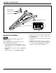
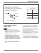
Figure 3-14: 7 Pin Connector Detail and Wiring Chart (After August, 2013)
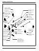
LED Light and SMV Bracket
Installation (2410-7-24) (After
August, 2013)
NOTES
• See Figures 2-1 thru 2-3 for light bracket
placement. If no dimension is given for a bracket, it
should be located against frame member as shown
in drawing.
• See Figure 3-13 for Light and SMV Bracket
Installation for 2410-7-24 model.
IMPORTANT
Make sure lights are positioned for maximum
visibility from the rear.
1. Attach left and right front brackets w/ yellow reflectors
and ag amber LED single lamps to frame using
1/4-20 x 1-1/4 hex head cap screws and hex lock
nuts (See Figure 3-13.)
2. Attach left and right rear brackets w/ red and orange
reflectors and ag amber LED single lamps to frame
using 1/4-20 x 1-1/4 hex head cap screws and hex
lock nuts.
3. Attach left tail light mount to frame assembly using
light mount bracket, 5/8-11 x 11-1/2 hex head cap
screws, and 5/8-11 hex lock nuts.
4. Attach ag flasher control module to right tail light
mount using 1/4-20 x 1-1/2 hex head cap screws and
hex lock nuts. Be sure that the control module is set
so that the 4 pin connector faces the right side of the
machine.
5. Attach right tail light mount w/ ag flasher control
module to frame assembly using light mount bracket,
5/8-11 x 11-1/2 hex head cap screws, and 5/8-11 hex
lock nuts.
6. Attach the ag red single LED lamps and reflector
assemblies to tail light mounts using 1/4-20 x 1-1/4
hex head cap screws and hex lock nuts.
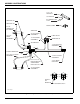
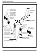
7. Attach front warning harness to frame. Connect 4 pin
end (A) to the two 34” extension harnesses (B and
C), and the ag flasher control module (C) (See
Figure 3-13.)
NOTE
Figure 3-13 is labeled with letters assigned for each
harness connection to assist in proper lighting intentions.
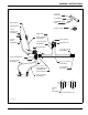
8. Install the rear warning light harness to the frame.
9. Connect 6 pin end of the ag flasher control module
(D) to the rear warning light harness (D).
10. Connect 2 pin ends to each of the splitter wiring
harnesses (E).
11. Connect short end of the splitter wiring harnesses
(F) to the front amber lights (F).
12. Connect long end of each splitter wiring harnesses
(G) to the rear amber lights (G).
13. Connect 3 pin ends of the rear warning light harness
(H) to each of the red tail lights. See Figure 3-14 for
LED harness wire designations.
14. Insure that the harnesses are clear of any moving
parts and secure the harnesses with tie wraps
provided.
15. Install the stor-away holder to hose holder on hitch
with 1/4-20 x 3/4 hex head cap screws and hex lock
nuts.
16. Attach SMV emblem and mounting bracket to rear
center frame bar using 1/2-13 x 5-1/2 hex head cap
screws, 1/4-20 x 3/4 hex head cap screws, and hex
lock nuts. The SMV sign should be centered on the
rear bar of the frame.
7-PIN
CONN
1
2
3
4
5
6
7
D
B
A
C
GROUND
WORK LAMPS
LEFT FLASHING
& TURN
STOP LAMPS
RIGHT FLASHING
& TURN
TAIL LAMPS
SWITCHED
POWER (12V)
4-PIN
TOWER
GROUND
BLACK
YELLOW
RED
GREEN
BROWN
BLUE
CIRCUIT WIRE
COLOR
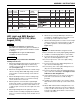
m177210 wire designations op
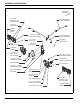
WIRE DESIGNATIONS FOR MAIN HARNESS WIRE DESIGNATIONS FOR REAR HARNESS
A
B
C
D
E
F
2-PIN
TOWER
1
2
3
4
5
3-PIN
TOWER
6-PIN
SHROUD
3-PIN
TOWER
2-PIN
TOWER
A
B
A
B
C
C
A
B
A
B